Foxconn NF4SLI7AA-8EKRS2 User Manual
Page 12
5
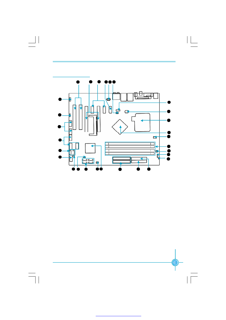
Chapter 1 Product Introduction
Note: The above motherboard layout is provided for reference only; please
refer to the physical motherboard.
1. FAN1
Connector
2. CD_IN Connector
3. Auxilialy PEX Power Connector
4. PCI Express x1 Slots
5. PCI Express x16 Graphics Slots
6. PCI Slots
7. Front Audio Connector
8. Speaker Connector
9. F_1394b Connectors
10. Front USB Connectors
11.SATA Connectors(Sil3132 support )
12. Front Panel Connector
13. BIOS TBL Enable Jumper
14. Clear CMOS Jumper
15. SATA Connectors(MCP-04 support )
16. SYS_FAN Connector
17.NVIDIA MCP-04 Chipset
18. IDE Connectors
19. Floppy Connector
20. 24-Pin ATX Power Connector
21. Chassis Intruder Connector
22. IrDA Connector
23. PWR_FAN
24. DDR DIMM Slots
25. CPU_FAN
26. NVIDIA Crush 19 Chipset
27. CPU Socket
28. ATX 12V Power Connector
29. COM2 Connector(optional)
Motherboard Layout
9
18
16 17
10
13
12
11
14
15
19
20
22
23
24
25
26
27
28
8
7
6
5
4
2
3
29
34
37
6
1
21
PDF 文件使用 "pdfFactory" 试用版本创建