Instructions for the installer – Fulgor Milano PH 905 G WK User Manual
Page 15
14
15
GB
Installation
This appliance is not provided with a combustion
product discharge. It is recommended that it be installed
insufficiently aerated places, in terms of the laws in force.
The quantity of air which is necessary for combustion
must not be below 2.0 m
3
/h for each kW of installed
power. See table of burner power.
Positioning (Fig. 4)
The appliance can be fitted into a working area
as illustrated on the corresponding figure. Before
positioning the hob, fit the seal around the entire
periphery of the hole cut in the worktop.
Fig. 4
Gas connection (Fig. 5)
Connect the appliance to the gas cylinder or to the
installation according to the prescribed standards
in force, and ensure beforehand, that the appliance
matches the type of gas available. Other wise, see
”Adaptation to various types of gas”. Further more,
check that the feed pressure fall swithin the values
described on the table: ”User chacteristics”.
Fig. 5
Rigid/semi rigid metalconnection
Carry out the connection with fittings and metal pipes
(even flexible pipes) so as to obtain counter stress the
inner parts of the appliance.
N.B. - when the installation has been carried out, check
the perfect sealing of the entire connection system, by
using a soapy solution.
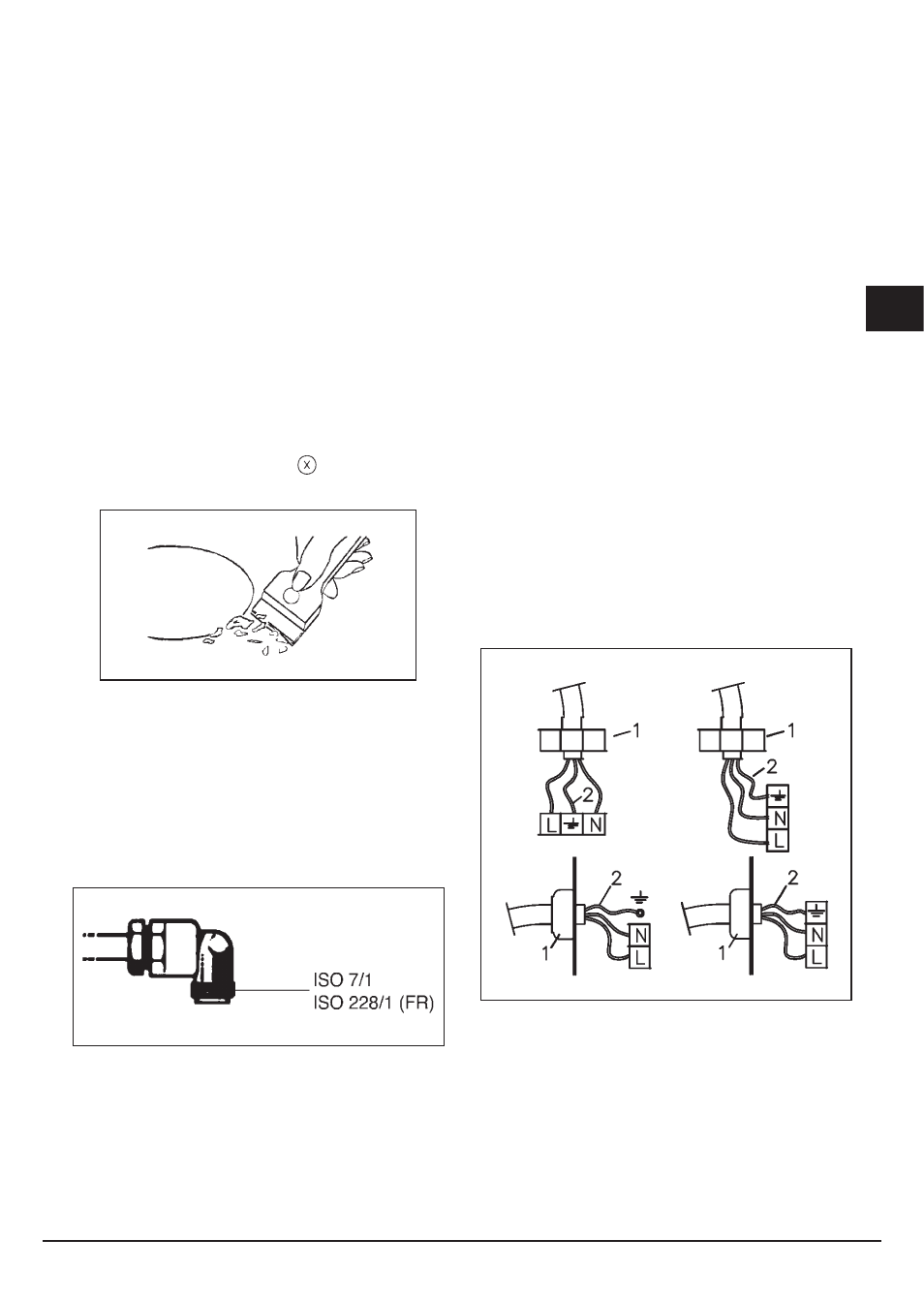
Electrical connection (Fig. 6)
Prior to carrying out the electrical connection, please
ensure that:
• the plant characteristics are such as to follow what is
indicated on the matrix plate placed at the bottom of
the working area;
• that the plant is fitted with an efficient earth connection,
following the standards and law provisions in force.
The earth connectionis compulsory in terms of the
law.
Should there be no cable and/or plug on the equipment,
use suitable absorption material for the working
temperature as well, as indicated on the matrix
plate. Under no circumstance must the cable reach a
temperature above 50°C of the ambient temperature.
If connecting directly to the mains power supply, fit a
multi-pole switch of a suitable size for the rated capacity
with a clearance distance which completely disconnects
the power line under overvoltage category III conditions,
consistently with the rules of installation (the yellow/
green earth wir must not be interrupted). The plug or
omnipolar switch must be easily reached on the installed
equipment.
Fig. 6
To avoid all risk, if the power cable becomes
damaged, it must only be replaced by the
manufacturer, by an authorised service centre, or by
a qualified electrician.
Instructions for the installer
1 - CABLE-CLAMP
2 - YELLOW/GREEN