Connection considerations, Wiring harnesses, Connecting to power – Fusion MS-UD650 Installation User Manual
Page 2
14
If necessary, place the nut plates
Á
behind the dashboard.
15
Place the stereo in the cutout.
16
Secure the stereo to the mounting surface using the included
screws
Â
.
17
If necessary, secure the back of the stereo with a back strap
or brace (not included).
Connection Considerations
The stereo must be connected to power, to speakers, and to
media input sources to function correctly. You should carefully
plan the layout of the stereo, the speakers, and your input
sources before making any connections.
Power and Speaker Wiring Harness Wire
Identification
Wire Function
Wire
Color
Notes
Power (+)
Yellow
This should be connected to a constant
12 Vdc source capable of supplying
15 A. All 12 V wiring must be fused at
the power source end of your cable
using a 15 A fuse.
Ground (-)
Black
This should be connected battery
negative before connecting the yellow
wire. All accessories connected to the
stereo must share a common ground
location.
Ignition
Red
This should be connected to a
separately switched 12 Vdc connection,
such as an ignition bus, to turn the
stereo on and off. If you are not using a
switched 12 Vdc connection, you must
connect this to the same source as the
yellow (power) wire.
Amplifier on
Blue
This is connected only when using an
optional external amplifier.
Telephone Mute
Brown
When connected to ground and a call is
received on a hands-free mobile phone,
this mutes the audio or switches the
input to AUX IN 2. This is configurable
in the settings menu.
Dim
Orange
This can be connected to the boat's
illumination wire to dim the stereo
screen when the lights are on.
This must be connected to a wire
gauge suitable for the fuse supplying
the circuit it is connected to.
Speaker zone 1
left (+)
White
Speaker zone 1
left (-)
White/
black
Speaker zone 1
right (+)
Gray
Speaker zone 1
right (-)
Gray/black
Speaker zone 2
left (+)
Green
Wire Function
Wire
Color
Notes
Speaker zone 2
left (-)
Green/
black
Speaker zone 2
right (+)
Purple
Speaker zone 2
right (-)
Purple/
black
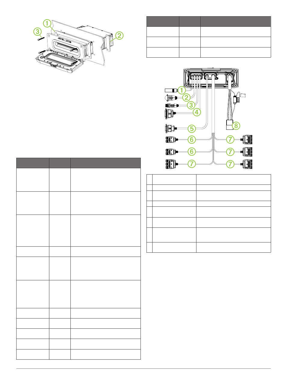
Wiring Harnesses
À
Antenna
Motorola-style standard antenna
connector
Á
ACCESSORY
SiriusXM
®
connector
Â
WIRED REMOTE
NMEA 2000
Connect to a NMEA 2000
®
network or a
Fusion wired remote
Ã
USB
USB-A industry standard
Ä
Varies by model
HDMI
®
and Ethernet: 750 models
Composite and component: 650 models
Å
AUX IN 1, AUX IN 2
Red and white RCA stereo line inputs for
sources such as CD and MP3
Æ
Zone connectors
Line outputs for speakers and subwoofer
amplifiers. 650 models have three zones.
750 models have four zones.
Ç
Power and speaker
wiring harness
Power and Speaker Wiring Harness
Connecting to Power
When connecting the stereo to power, you must connect both
power wires. The yellow power wire should be connected
directly to the battery, or connected using a 15 A isolator switch.
This provides power to the stereo and a constant trickle-power
standby feed. The red signal wire should be connected to the
same battery through the ignition or another manual switch to
turn the stereo on and off.
If you are not routing the red wire to the ignition or another
manual switch, you can connect the yellow to the red, and
connect them to the positive (+) battery terminal. You should put
a fuse on the red wire.
If it is necessary to extend the yellow power and black ground
wires, use 14 AWG (2.08 mm
2
) wire. For extensions longer than
1 m (3 ft.), use 12 AWG (3.31 mm²) wire.
If it is necessary to extend the red signal wire, use 22 AWG
(0.33 mm
2
) wire.
1
Route the yellow power
À
and black ground
Á
wires to the
battery and route the wiring-harness plug to the stereo.
Do not connect the wiring harness to the stereo until all of the
bare wire connections have been made.
2