Groth 1800A User Manual
Page 7
Page 7 of 17
WARNING: When assembling a P/V valve, always use the correct length stem (as specified in
Table 3), put the pressure and vacuum pallet assemblies back in their original location and ensure
that the stem is straight and fits into the guide in the cover or weatherhood.
1. If the stem length is too long, pallet lift will be restricted; the valve will not attain its full rated
flow capacity.
2. If the pressure and vacuum pallet assemblies are mixed at assembly, the settings will be
changed and pallet lift may be completely blocked. An over-pressure can occur if any of these
three conditions happens. This can cause a tank failure, severe personal injury and material
damage.
Valve
Size
(In)
Table 3 - Stem Length
Pressure Port
Vacuum Port
Pipe-Away
in (cm)
Weatherhood
in (cm)
Side Mount
in (cm)
All Others
in (cm)
2
5.25 (13.34)
7.44 (18.90) N/A 4.69
(11.91)
3
6.88 (17.46)
7.44 (18.90)
5.25 (13.34)
5.81 (14.77)
4
8.94 (22.70)
8.94 (22.71)
6.88 (17.46)
7.13 (18.10)
6
11.94 (30.32)
11.75 (29.85)
8.94 (22.70)
8.88 (22.54)
8
13.56 (34.45)
11.94 (30.33)
11.94 (30.32)
10.88 (27.62)
10
14.94 (37.94)
10.88 (27.64)
13.56 (34.45)
12.63 (32.07)
12
16.56 (42.07)
11.75 (29.85)
14.94 (37.94)
14.94 (37.94)
14 N/A
N/A
16.56
(42.07)
N/A
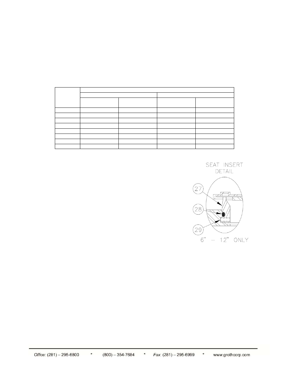
Seat Replacement (6" – 12" only)
1. The insert is retained in the casting by [3] stainless steel
socket head set screws threaded radially through the
insert. See Figure 6.
2. Remove the screws [#29] with a hex wrench. The screws
were installed with Lok-Tite thread sealant, so you may
need some heat to break them loose.
3. Remove the insert [#27] from the casting by applying force
uniformly around the perimeter. The O-Ring [#28] will
resist removal, but there is a groove between the insert
and casting where force can be applied.
4. Replace or re-install the seat insert with a new O-Ring
[#28]. Lightly coat the O-Ring [#28] with grease and install
into the groove in the insert [#28].
5. Install insert [#27] in the casting and press in all around
until insert is in firm metal-to-metal contact with the
casting.
6. Apply 3-4 drops of Lok-Tite thread sealant to each of the
[3] set screws and insert them into the insert until they contact the casting hand-tight.
Figure 6 – Seat Insert Detail