Inspection and installation – Groth 1201B User Manual
Page 6
6
INSPECTION AND INSTALLATION
The pressure/vacuum relief valve is carefully packaged to prevent damage or contamination during shipping. Inspect
all equipment when it is received; report any damage to the carrier immediately. The valve should be protected
during handling and storage. Keep all the ports plugged to prevent intrusion of foreign materials. Before installation,
inspect the unit for indications of physical damage or internal contamination. If these are observed, the valve must be
disassembled, cleaned and repaired before installation.
Groth's spring loaded PV Valves are designed to provide tank protection for set-pressures to 15 PSIG and vacuum to
12 PSIG. The valves provide full rated flow capacity at 100% over-pressure. Consult factory for performance under
other conditions.
The valve should be installed in a vertical position as shown in Figure 1.
Follow the torque guidelines listed in Table 2 to avoid produce damage due to excessive fastener tightening. The
valves are NOT rated for full flange pressure and do not require high bolting torque. Consult factory for special
applications; torque values assume a maximum MAWP of 30 PSIG.
The following guidelines should be observed at installation:
1. Remove any flange protectors and discard all packing material.
2. Inspect the gasket seating surface of the tank nozzle flange. It must be clean, free of scratches, corrosion, tool
marks, and flat.
3. Aluminum valves are furnished with flat face flanges; they should only be installed on a mating flat faced flange
with a full faced gasket.
4. Inspect the gasket; make sure that the material is suitable for the application.
5. Lubricate all studs and nuts with an appropriate thread lubricant. If the valve will see high temperature service or
stainless steel fasteners are used, select an anti-seize compound such as moly-disulfide.
6. Center the gasket within the bolt circle.
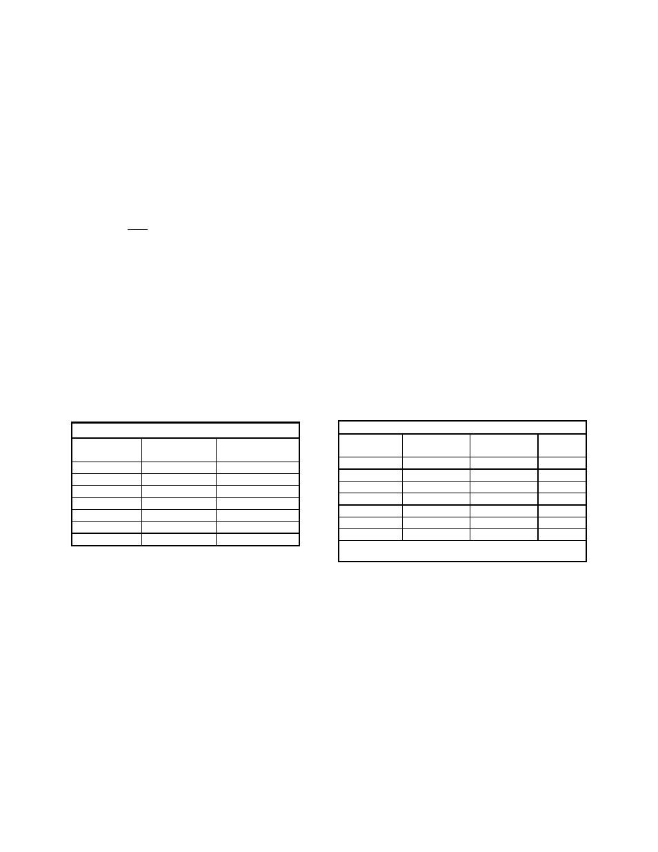
7. Set the valve carefully on the nozzle. Install the studs and tighten nuts hand tight. For stud selection for blind
tapped holes see Table 1 below:
TABLE 1: STUD SELECTION
I
nlet Flange
Thread
Size
Recommended
Stud Length
2"
5/8" - 11
2.25"
3"
5/8" - 11
2.50"
4"
5/8" - 11
2.50"
6"
3/4" - 10
3.00"
8"
3/4" - 10
3.00"
10"
7/8" - 9
3.50"
12"
7/8" - 9
3.50"
8. Torque all fasteners to half the value listed in the table below in a staggered, alternating pattern.
9. Make sure that the flanges are not distorted and that the gasket is evenly compressed.
10. Make up the final torque and check that no further nut rotation occurs at the specified torque value, as specified in
Table 2.
TABLE 2: BOLT TORQUE CHART, LB-IN [N-m]*
Inlet Flange
Raised Face
Flat Face
Number
Bolts
2"
30 [3.4]
60 [6.8]
4
3"
54 [6.1]
108 [12.2]
4
4"
42 [4.7]
78 [8.8]
8
6"
90 [10.2]
150 [16.9]
8
8"
126 [14.2]
228 [25.8]
8
10"
138 [15.6]
246 [27.8]
12
12"
186 [21.0]
348 [39.3]
12
*Average values based on a nitrile binder synthetic gasket,
1/32" thick and lubricated threads.