Gullco GK-200-RLx-L User Manual
Page 8
6
WARNING! The motor and oscillator controls must not be continually started and stopped by the
removal and reapplying of power to the controls. Turning the power off to the controls
will not provide instant braking and continued use will damage the controls. Allow ten
(10) seconds after the removal of power before reapplying the power to the
equipment.
The Fuse Holder allows accessibility to the main fuse by pushing the cap in towards the main body
and twisting in a counter-clockwise direction.
The Arc Activation Signal Connector is used to interface with the trigger signal of the customers
welding equipment and is used to start/stop the welding process.
Either the Linear or Radial model of compact oscillator head can be plugged into the Oscillator
Head Connector (control needs to be calibrated to suite the type of head).
"KAT"
®
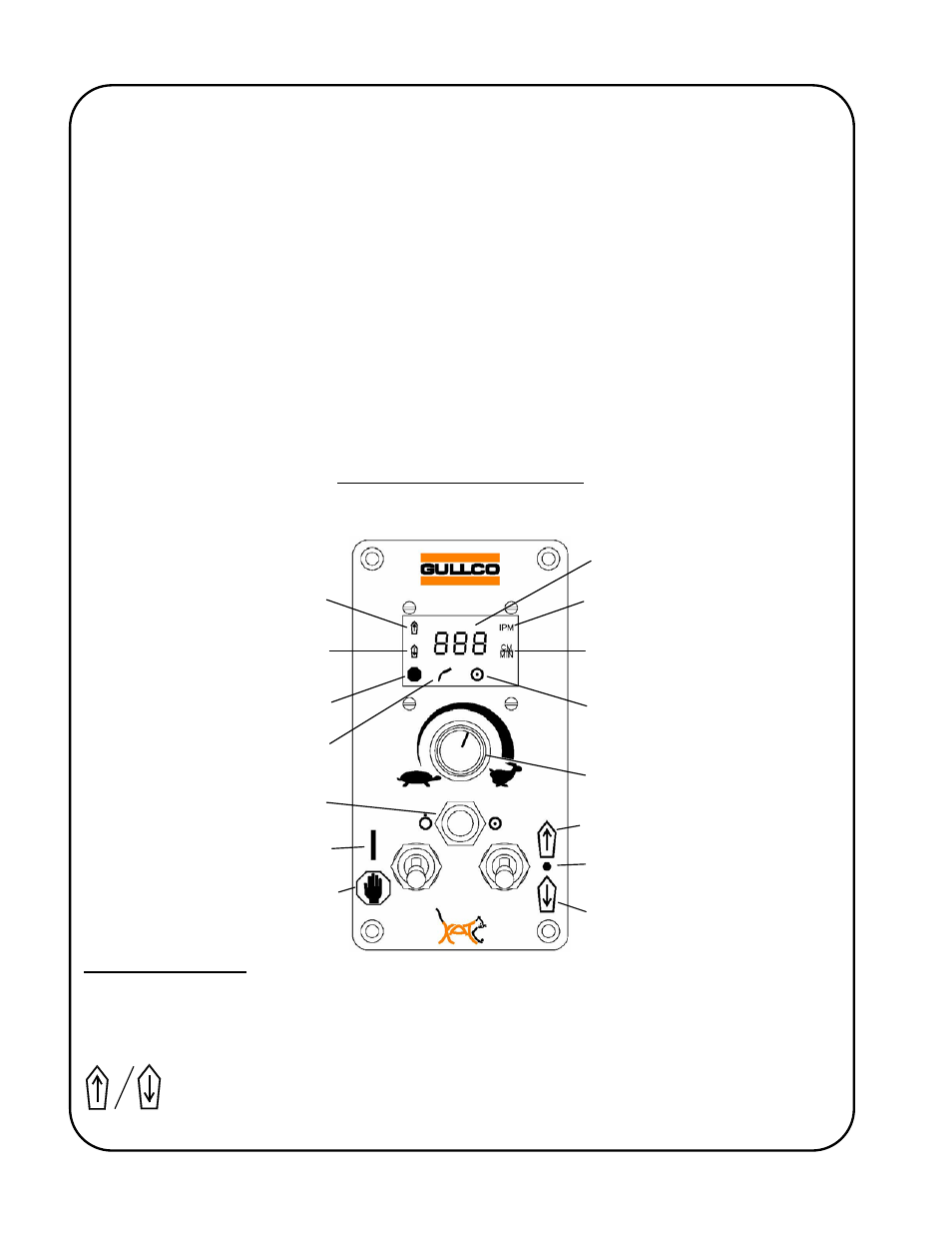
CONTROL (GSP-2100)
The L.E.D. Display
The control has an L.E.D. display that indicates the travel speed in either inches per minute or
centimetres per minute. The display also shows the travel direction accessed as well as the status
of the Stop command.
The Forward and Reverse L.E.D.’s indicate the “KAT”
®
carriage motor direction
commanded.
Speed & Parameter Value
Display
Speed Display Calibrated in
Inches per Minute
Speed Display Calibrated in
Centimeters per Minute
Auto Cycle Mode (Constant)
Manual Mode (Absent)
Speed Adjustment
Counter-Clockwise = Slower
Clockwise = Faster
Neutral
Command Reverse Motion
Control in Run Mode
Cycle Push Button
Arc Signal Active
Hold (Stop) Mode Active
Reverse Motion Commanded
Forward Motion Commanded
Control in Hold (Stop) Mode
Command Forward Motion