Install air control box -5, Installation – Hypertherm HT400 Air Injected Water Muffler System User Manual
Page 16
Page 2-5
INSTALLATION
Air Injected Water Muffler System
Instruction Manual
lag problems during startup, resulting in excessive noise and smoke during initial
starting. If more than four feet (1.2 m) of hose is required, it is recommended
that solid tubing be used up to a maximum length of eight feet (2.4 m). If solid
tubing is to be installed,
do not use PTFE tape
. Use liquid pipe-thread sealant
only.
The pump must
be below the water level of the water table in order to function
properly.
2.
Install the suction filter/strainer (# 027009) to the water table feed port. Figure
2-2 represents an optional installation; the user may wish to use another configu-
ration. The reducer bushing (# 015578) and nipple (# 015509) are supplied;
other required filter/strainer connection and support hardware are customer
supplied.
3.
Connect the pump inlet to the filter/strainer assembly using the supplied four-foot
hose assembly (# 024023) or solid tubing (eight feet [2.4 m] maximum). See
Figure 2-3.
4.
Route the pump discharge hose assembly (# 024022) from the pump to the
nozzle assembly through the power track or festoon system. In no case should
the discharge hose be longer than 80 feet (24.4 m).
Note: If the discharge hose is routed in an overhead festoon system, a check
valve may be required. To determine if a check valve is needed, refer to
the
Pump Discharge Hose Water Recovery Checkout
at the back of this
section.
5.
Connect three-conductor cable (# 023445, 50 ft. [15.3 m]) to the water muffler
pump contactor (AC and ground). Refer to Water Muffler/Pump Cable table
below.
6.
Connect the plug end of the cable to the receptacle on the rear of the power
supply labled W-M PUMP.
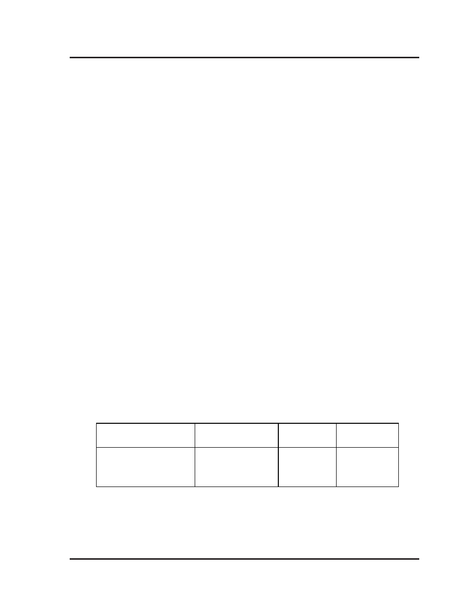
Water Muffler/Pump Cable
Install Air Control Box
1.
Mount the air control box to a convient location on the cutting machine, so that it
is no farther than 10 feet (3 m) from the W-M nozzle assembly.
Color
Black
White
Green
Function
W-M Coil
AC Neutral
Ground
To W-M Pump
Contactor
Coil
AC Neutral
Ground
From Power Supply
W-M Pump Recp/Plug
2
4
3
8-94