Installation, Page 2-8 – Hypertherm HT400 Air Injected Water Muffler System User Manual
Page 19
INSTALLATION
Page 2-8
Air Injected Water Muffler System
Instruction Manual
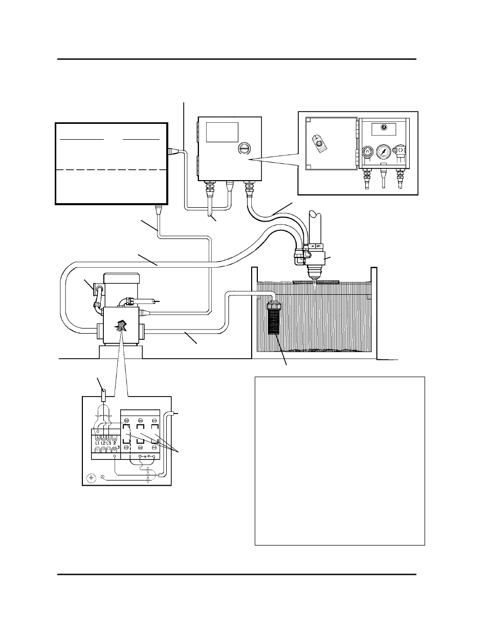
Figure 2-3 Air Injected Water Muffler System Interconnection Diagram
7-96
SET
OFF
ON
Input Power *
Nozzle Assembly
Filter/Strainer
Detail of
Air Control Box
Input Power*
AIR OUT Hose (# 024022)
Detail of
Contactor Box
Contactor
Pump
Air Control Box
AIR IN Supply Hose
(Customer Supplied)
Pump Outlet Hose (# 024022)
Pump Inlet Hose (# 024023)
120 VAC Relay Power Cable
(# 023445 3-Cond.)
Water Table
PS/Air Control Box
Cable (5-Cond.)
(Refer to page 2-6 for
part numbers)
Power Supply
Connector Label
Power Supply
W-M AIR 1X9
HT4000
W-M AIR 1X11
HT4001
WATER MUFFLER (W-M AIR)
11 RECP
HT400
W-M PUMP 1X8
HT4000
W-M SUPPLY 1X10
HT4001
WATER SUPPLY (W-M PUMP)
12 RECP
HT400
* 230/460V, 3 PH, 60 Hz
380/415V, 3 PH, 60 Hz
575V, 3 PH, 60 Hz
Contactor
Heater Location
120 VAC Relay Power
Cable
(# 023445 3-Cond.)
Link Box
Notes:
The 240/480V water muffler pump is shipped to
operate at 480V. The 380/415V pump is shipped to
operate at 380V. See tag on the pump to link for
alternate voltages. Link box is located on the pump
housing (see drawing).
The 240/480V and 380/415V pumps are shipped
with two sets of 3 contactor heaters located in the
contactor box. See the chart below to determine
which heater to use.
Heater
Hypertherm
Voltage
Amps
Label
Part No.
240V (230V)
6.06
W45
003170
380V
3.00
W38
003029
415V
3.00
W38
003029
480V (460V)
3.00
W38
003029
600V (575V)
2.45
W36
003171