IBASE MI890 User Manual
Page 18
Advertising
INSTALLATIONS
14
MI890 User’s Manual
J4: DC_IN Connector
Note: J4 input voltage is +12V only.
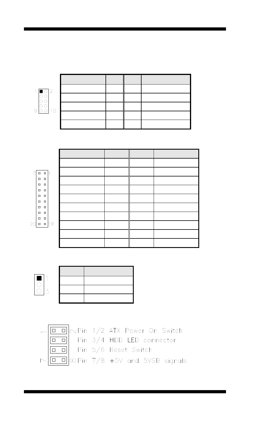
J5: Digital I/O
Signal Name Pin Pin
Signal Name
GND
1
2
VCC
OUT3
3
4
OUT1
OUT2
5
6
OUT0
IN3
7
8
IN1
IN2
9
10
IN0
J6: COM3/ COM4 RS232 Serial Ports (option)
Signal Name Pin #
Pin #
Signal Name
DSR1
2
1
DCD1
RTS1
4
3
RXD1
CTS1
6
5
TXD1
RI1
8
7
DTR1
NA
10
9
Ground
DSR2
12
11
DCD2
RTS2
14
13
RXD2
CTS2
16
15
TXD2
RI2
18
17
DTR2
NA
20
19
Ground
J8: Power LED Connector
Pin #
Signal Name
1
+5V
2
NC
3
Ground
J9: System Function Connector
J10: SPI Flash Connector (factory use only)
Advertising