IBASE MI805 User Manual
Page 29
Advertising
INSTALLATIONS
MI805 User’s Manual
25
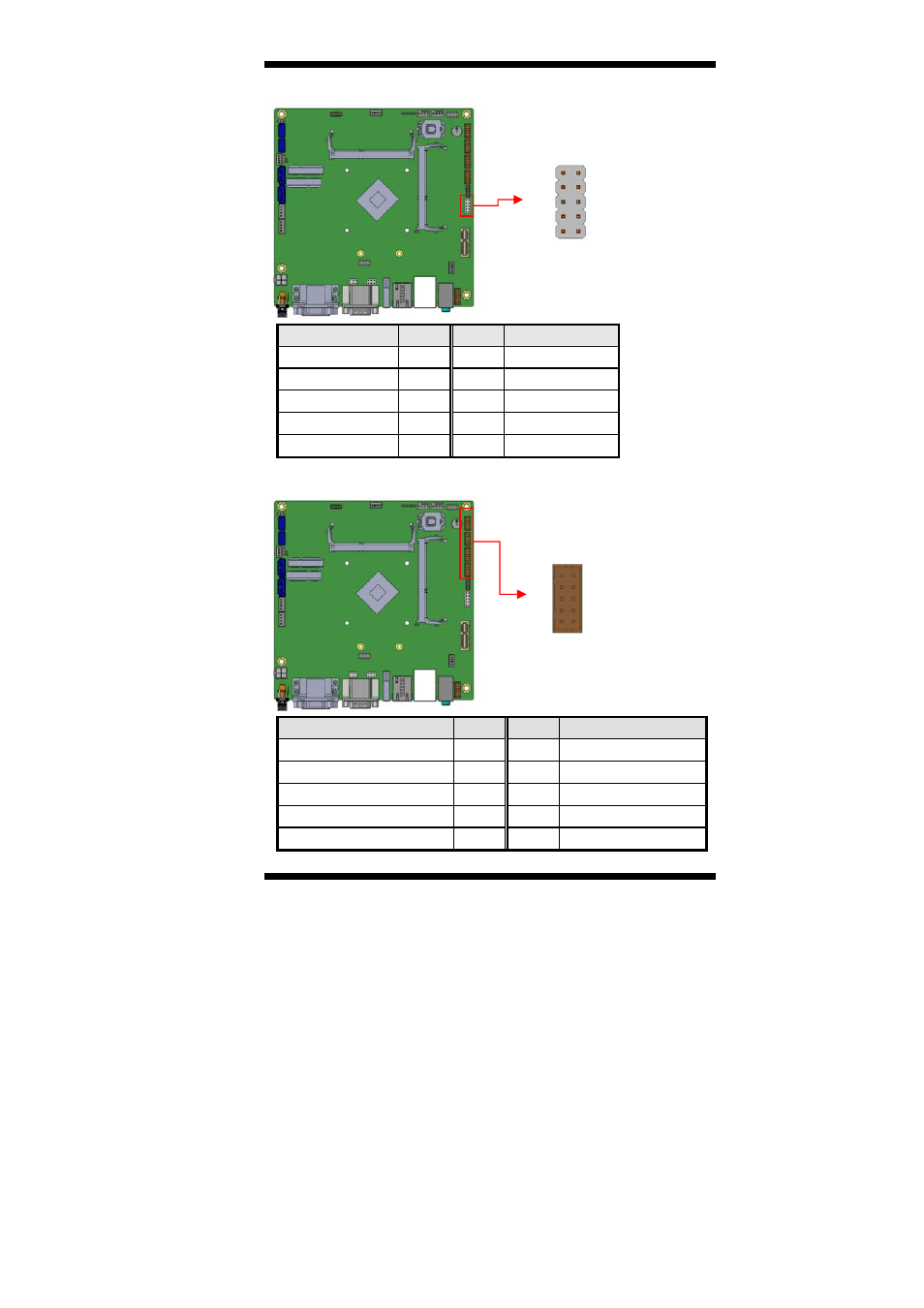
J17: Digital I/O
[
Signal Name
Pin #
Pin #
Signal Name
GND 1
2 VCC
OUT3 3
4 OUT1
OUT2 5
6 OUT0
IN3 7
8 IN1
IN2 9
10
IN0
J18, J19, J20, J21: COM6/COM5/COM4/COM3
Signal Name
Pin #
Pin #
Signal Name
DCD, Data carrier detect
1
2
RXD, Receive data
TXD, Transmit data
3
4
DTR, Data terminal
GND, ground
5
6
DSR, Data set ready
RTS, Request to send
7
8
CTS, Clear to send
RI, Ring indicator
9
10
Not Used
9
1
10
2
10
2
9
1
Advertising