IBASE MB968 User Manual
Page 21
Advertising
INSTALLATIONS
21
Pins 19, 20: HDD LED
This connector connects to the hard drive activity LED on control
panel. This LED will flash when the HDD is being accessed.
Pin #
Signal Name
19
+3.3V
20
-HDD_LED
J5: VGA Connectors
Signal Name
Pin #
Pin #
Signal Name
VGA_R
1
2
VGA_PWR
VGA_G
3
4
GND
VGA_B
5
6
NC
NC
7
8
VGADDCDATA
GND
9
10
HSYNC
GND
11
12
VSYNC
GND
13
14
VGADDCCLK
GND
15
J6, J7, J8: USB6~USB11 Ports
Signal Name Pin #
Pin #
Signal Name
+5V
1
2
GND
D-
3
4
D+
D+
5
6
D-
GND
7
8
+5V
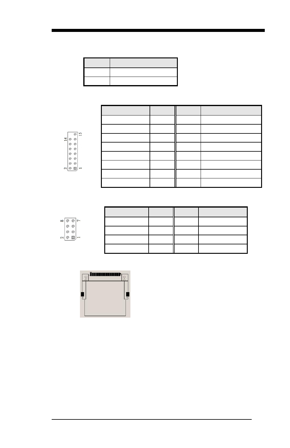
J9: Compact Flash Socket
Note: CF card supports IDE mode only.
If CF card applied, please set the SATA configuration to “IDE
mode” in BIOS.
J10: Mini PCI- E / mSATA Socket
J11: SPI Debug Port
Advertising