Installations – IBASE MB968 User Manual
Page 7
INSTALLATIONS
7
USB Ports
Two USB 3.0 + 2.0 ports at front panel
One USB 2.0 for Mini PCI-e
Six USB 2.0 pin headers (pitch 2.54)
Network
Bypass
Two segment hardware Bypass (Eth5 & 6; Eth7 & 8)
Bypass mode selection in BIOS
LPC I/O
Fintek F81866AD-I (128-pin LQFP [14mm x 14 mm])
COM1: RJ-45 Console x1
COM2~4: RS-232 [2x5] Pin Header Onboard x3
Hardware monitors
Fan Connector x4
Digital IO 4in & 4 Out
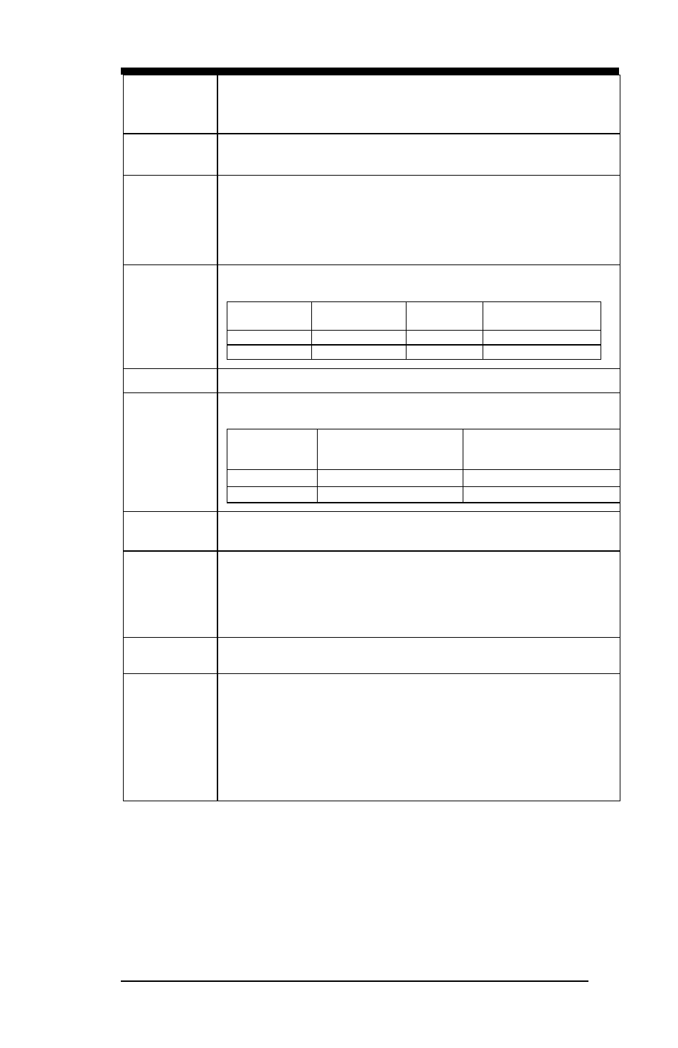
Smart Fan
Control
The active temperature may be adjusted based on system thermal test
result. All reference to CPU temperature.
Active
Temperature
Tolerance
Default Smart Fan
Enable or Disable
CPU Fan
50
+/- 5
Enable
System Fan
50
+/- 5
Enable
RTC
Intel C226 built-in RTC with on-board lithium battery & holder
Expansion
Slot
(CPU PEG
port)
CPU jumper setting PEG port to following configurations for golden
fingers & riser cards
Configuration
Golden Finger #1
Compatible Riser Cards
Golden Finger #2
Compatible Riser Cards
1
IP332
IP331
N/A
2
IP333
IP333
IP331 or IP333
Expansion
Interface
Mini PCI-e Socket x1 (m-SATA compatible)
Mini PCI-e Socket x1 (support m-SATA only)
Front Panel
Buttons &
Connector
Two RJ-45 1x4 connectors for Eth1~4 & 5~6
USB 3.0 x2
RJ-45 (for console, COM1)
Three LEDs for Power, Bypass or HDD & Status
Factory Mode Restore Reset Switch
Rear I/O
interface
PSU AC inlet
1x or 2x Slot (Depend on product SKU)
Jumper /
Pin Header /
Switch
AT or ATX mode selection jumper
ATX mode power on / off pin header
Power on LED pin header
HDD active LED pin header
System Reset pin header
Clear CMOS
Clear ME RTC
Golden finger (1x16 or 2x8) switch jumper