J6: system function connector – IBASE IB885 User Manual
Page 22
INSTALLATIONS
J1 J2: COM3/4/5/6 Serial Ports
J1 - COM3/4 pin-header connector.
Pin1~Pin10 COM3
Pin11~Pin20 COM4
J2 - COM5/6 pin-header connector.
Pin1~Pin10
COM5
Pin11~Pin20
COM6
Signal Name
Pin #
Pin #
Signal Name
DCD, Data carrier detect
1
2
DSR, Data set ready
RXD, Receive data
3
4
RTS, Request to send
TXD, Transmit data
5
6
CTS, Clear to send
DTR, Data terminal ready
7
8
RI, Ring indicator
GND, ground
9
10
Not Used
DCD, Data carrier detect
11
12
DSR, Data set ready
RXD, Receive data
13
14
RTS, Request to send
TXD, Transmit data
15
16
CTS, Clear to send
DTR, Data terminal ready
17
18
RI, Ring indicator
GND, ground
19
20
Not Used
CN1: LPC I/F connectors
Package list:
COM port cable (PK1-20B) x2; Nylon Nut x1;
Screw x2; Washer x2
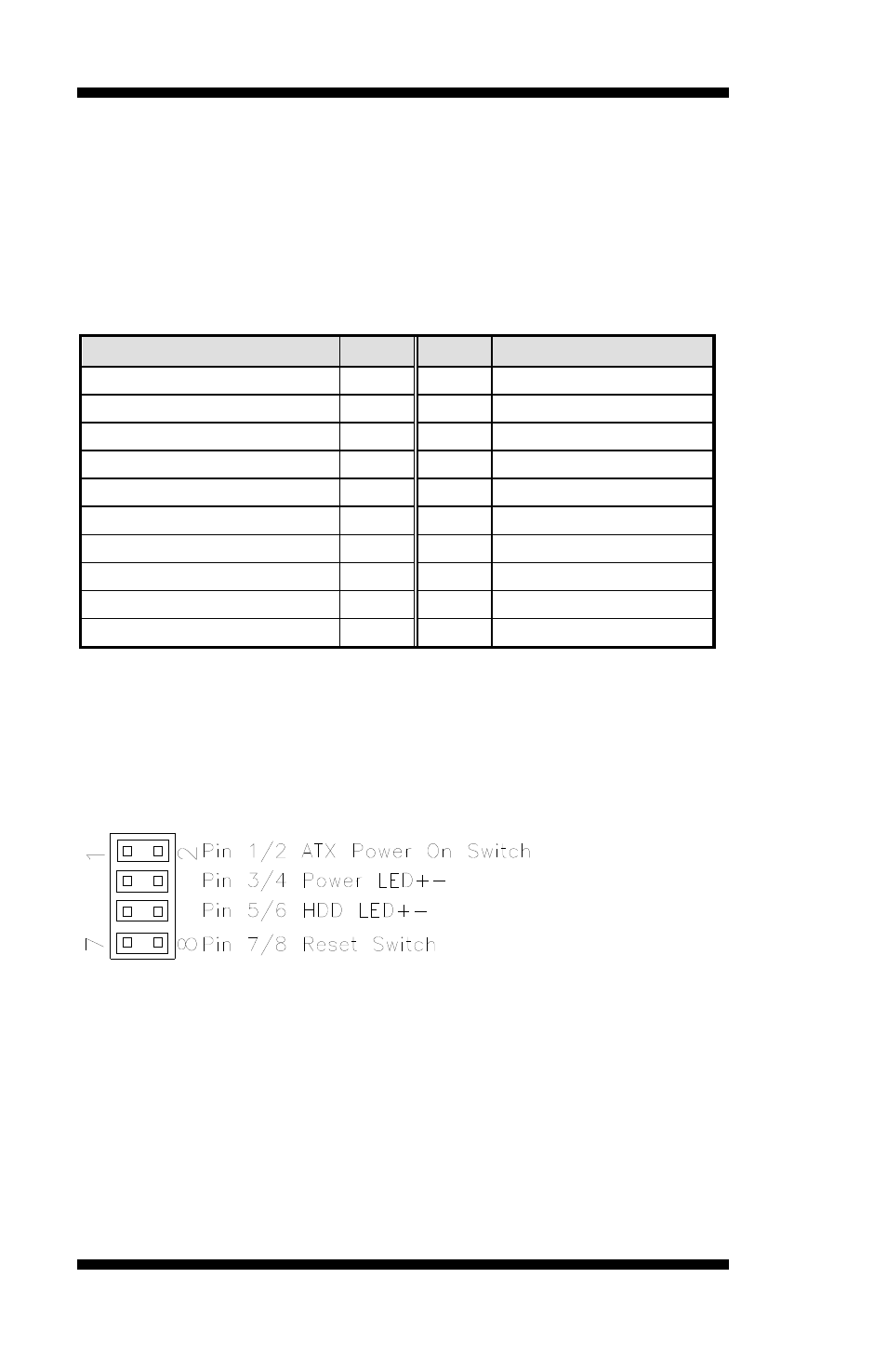
J6: System Function Connector
ATX Power ON Switch: Pins 1 and 2
This 2-pin connector is an “ATX Power Supply On/Off Switch” on the
system that connects to the power switch on the case. When pressed, the
power switch will force the system to power on. When pressed again, it
will force the system to power off.
18
IB885 User’s Manual