Signal name, J15: vga connector, J16: digital i/o – IBASE IB950 User Manual
Page 24: J17: spi flash connector (factory use only)
INSTALLATIONS
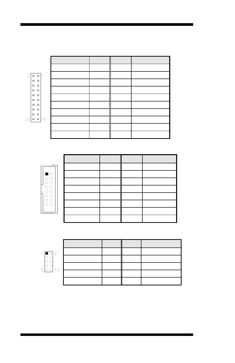
J14, J13: LVDS Connectors (1st channel, 2nd channel)
The LVDS connectors on board consist of the first channel (J14) and
second channel (J13) and supports 18-bit or 24-bit.
Signal Name
Pin #
Pin #
Signal Name
TX0- 2
1 TX0+
Ground 4 3 Ground
TX1- 6
5 TX1+
5V/3.3V 8 7 Ground
TX3- 10
9 TX3+
TX2- 12
11 TX2+
Ground 14 13 Ground
TXC- 16
15 TXC+
5V/3.3V 18 17 ENABKL
+12V 20
19 +12V
J15: VGA Connector
[
[
2
Signal Name Pin #
Pin # Signal Name
Red 1
2 5V
Green 3 4 GND
Blue 5
6 N.C.
N.C. 7
8
DDC_data
GND 9
10
HSYNC
GND 11
12
VSYNC
GND 13
14
DDC_clk
GND 15
J16: Digital I/O
Signal Name
Pin #
Pin #
Signal Name
GND 1
2 VCC
OUT3 3
4 OUT1
OUT2 5
6 OUT0
IN3 7
8 IN1
IN2 9
10 IN0
J17: SPI Flash Connector (factory use only)
20
IB950 User’s Manual