IBASE IP510 User Manual
Page 19
INSTALLATIONS
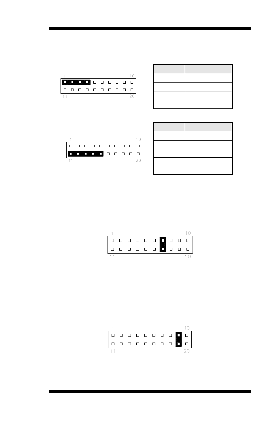
Speaker: Pins 1 - 4
This connector provides an interface to a speaker for audio
tone generation. An 8-ohm speaker is recommended.
Pin #
Signal Name
1 Speaker
out
2 No
connect
3 Ground
4 +5V
Power LED: Pins 11 - 15
Pin #
Signal Name
11 Power
LED
12 No
connect
13 Ground
14 No
connect
15 Ground
ATX Power ON Switch: Pins 7 and 17
This 2-pin connector is an “ATX Power Supply On/Off
Switch” on the system that connects to the power switch on
the case. When pressed, the power switch will force the
system to power on. When pressed again, it will force the
system to power off.
Reset Switch: Pins 9 and 19
The reset switch allows the user to reset the system without
turning the main power switch off and then on again.
Orientation is not required when making a connection to
this header.
IP510 User’s Manual
15