Main parts and connections, Lifting the equipment, Filler wire materials and equipment – Kemppi Promig 200 ML User Manual
Page 5: Filler wires and wire feed
PROMIG 200ML/0520 – 5
© KEMPPI OY
G
C
H
E
I
B
F
D
A
J
K
L
M
E
D C
A
F
B
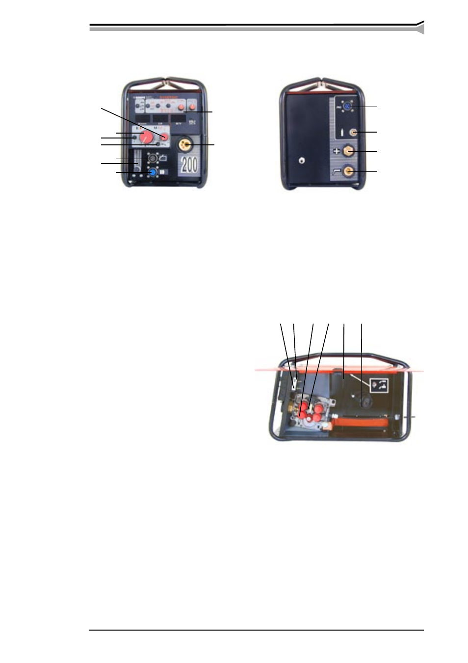
Inside
A
Selection of air/liquid cooling
B
Wire reel locking
C
Wire inch
D
Gas test
E
Tightening screw
F
Feed roll
2.5. LIFTING THE EQUIPMENT
For transferring the equipment or a part of it, use the machine handles. Machines can be lifted
with ropes. Fasten the ropes carefully round the machine. Note! Check that the machine can not
move vertically between the ropes.
2.6. FILLER WIRE MATERIALS AND EQUIPMENT
2.6.1. Filler wires and wire feed
Choose contact tube, wire conduit and feed roll according to welding wire. Filler wires and the
corresponding wire feed equipment are presented in the following scheme. The factory assembly
includes feed rolls with plain groove and with orange wire guide tubes for welding filler wires of
0.9-1.2 mm (0.035”, 0.045” and 0.052”).
Back side
Connections:
J
Control cable to power source
K
Shielding gas hose (snap connector)
L
Welding current cable
M
Connection for MMA
Front machine
A
Welding voltage (MIG)
B
Wire feed speed (MIG) / Welding
current (MMA)
C
Main switch
D
Control mode
E
Flowmeter / regulator for shielding
gas
F
Function panel
Connections:
G
Control cable of remote control
H
Control cable connector for sub-
feeder / motorized gun
I
Welding gun cable
2.4.2. Main parts and connections