Kleenmaid LWK300 User Manual
Lwk300 ironing centre
107842 Issue A
ECN: 04053
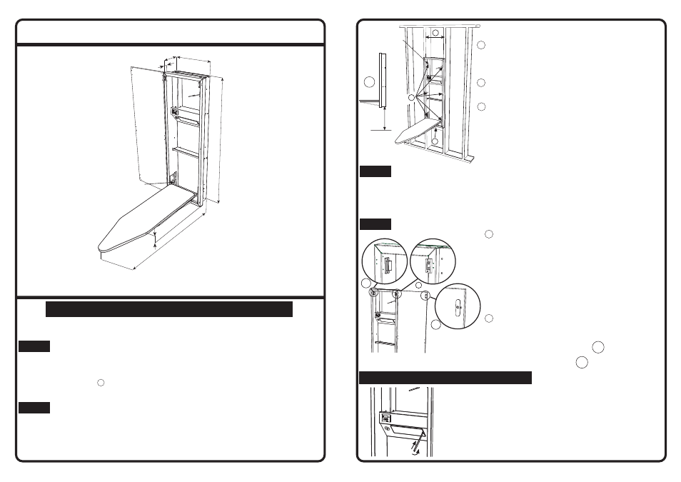
SPECIFICATION DIAGRAM
Model
LWK300
(Dimensions in mm)
I N S T A L L A T I O N I N S T R U C T I O N
NOTE: The LWK300 Ironing Centre can be mounted in two ways: Recessed Mount
and Surface Mount. For Surface Mount an additional decorative collar can be
purchased (Product Code LWK330).
PRELIMINARY INSTRUCTIONS
Remove the Packing Stops with small flat screwdriver from the Ironing Board
assembly. Ascertain from the user the DESIRED HEIGHT of the Ironing Board
when in the open position. We recommend an ironing surface height of 830mm
above the floor for an average adult. To obtain this surface height, the height of
the unit (see diagram A on next page) must be 680mm above the floor
(NOTE: 830mm is based on the second or middle position of the ironing board).
STEP 1
STEP 2
SURFACE MOUNT OPTION
Make sure solid timber studs or mounting points are in suitable position for the
mounting of the Ironing Centre. Drill through the back of the cabinet and fasten the
six screws supplied (it may be necessary to purchase different length screws for
correct fitting, or use wall anchors if unit is to be mounted to solid wall).
Note: Ironing Centre Collar (Product Code LWK330) is also available.
MOUNTING INSTRUCTIONS
PLEASE READ THE ENTIRE INSTRUCTION BEFORE
INSTALLING THE LWK300 IRONING CENTRE
1. Disconnect LWK330 Ironing Centre from power supply.
(Ensure the power is switched off)
2. Insert small screwdriver or slim knife as shown, ease
catch to side and slip out diffuser.
3. Replace lamp (40 watt max.)
4. Slide diffuser back into aperture and “click” into place.
(Turn power back on)
RECESS MOUNT OPTION
1 SIZE OF WALL OPENING
The LWK300 Ironing Centre is designed to fit
between 362mm studs. Take out a section of the
wall and insert two timber studs vertically at
362mm apart.
2 ATTACH BRACE
Attach horizontal brace between the studs at the
desire height. Ensure that the brace is level.
3 MOUNT CABINET
Lift cabinet into place, rest the cabinet on
horizontal brace, plumb and shim cabinet to fit,
and attach to studs using the supplied screws.
Mounting hole positions are indicated by the
arrows. Remove the wireway cover to access
mounting hole. Be sure to allow for wall covering
thickness behind cabinet face frame.
STEP 3
CONNECTING THE LWK300 IRONING CENTRE TO ELECTRIC POWER
An external ON/OFF (safety) switch for the LWK300 Ironing Centre must be installed
near the unit. An additional power socket can be installed inside the wall between
the switch and power plug. Alternatively the unit can be hard wired directly to the
switch by an electrician. For surface mount, the LWK300’s plug and lead can be
easily plugged into a nearby wall socket, or can be hard wired by an electrician.
STEP 4
DOOR ASSEMBLY INSTRUCTIONS
1 Mounting the Cabinet Door
hDoor may be hinged from either side of the
cabinet (illustration is shown for right side
hinging). Both sides of the cabinet have pre-
punched holes.
hUse the two hinges supplied to fix door to the
cabinet.
hAttach the hinges to door and cabinet using
the screws supplied at the top and bottom
section of the cabinet.
hUse the decorative plugs supplied to cover
the unused pre-punched holes.
2 Fixing Magnetic Catch
hMagnetic catch is fixed opposite to the hinge.
hFixing position is located on the top section of
the cabinet and the door.
hAttach the magnetic catch 2A onto cabinet
using the screws supplied.
hAttach the strike plate 2B onto door using the
screw supplied.
2A
2B
1
L A M P R E P L A C E M E N T
680
FLOOR
A
1
2
3
Wireway Cover
LWK300 Ironing Centre
PACKING STOPS
1248
1218
45
145
360
140