Kleenmaid LWK330 User Manual
Lwk330 ironing centre collar, Warning
LWK330 IRONING CENTRE COLLAR
PLEASE READ THE ENTIRE INSTRUCTIONS BEFORE
ASSEMBLING THE COLLAR KIT
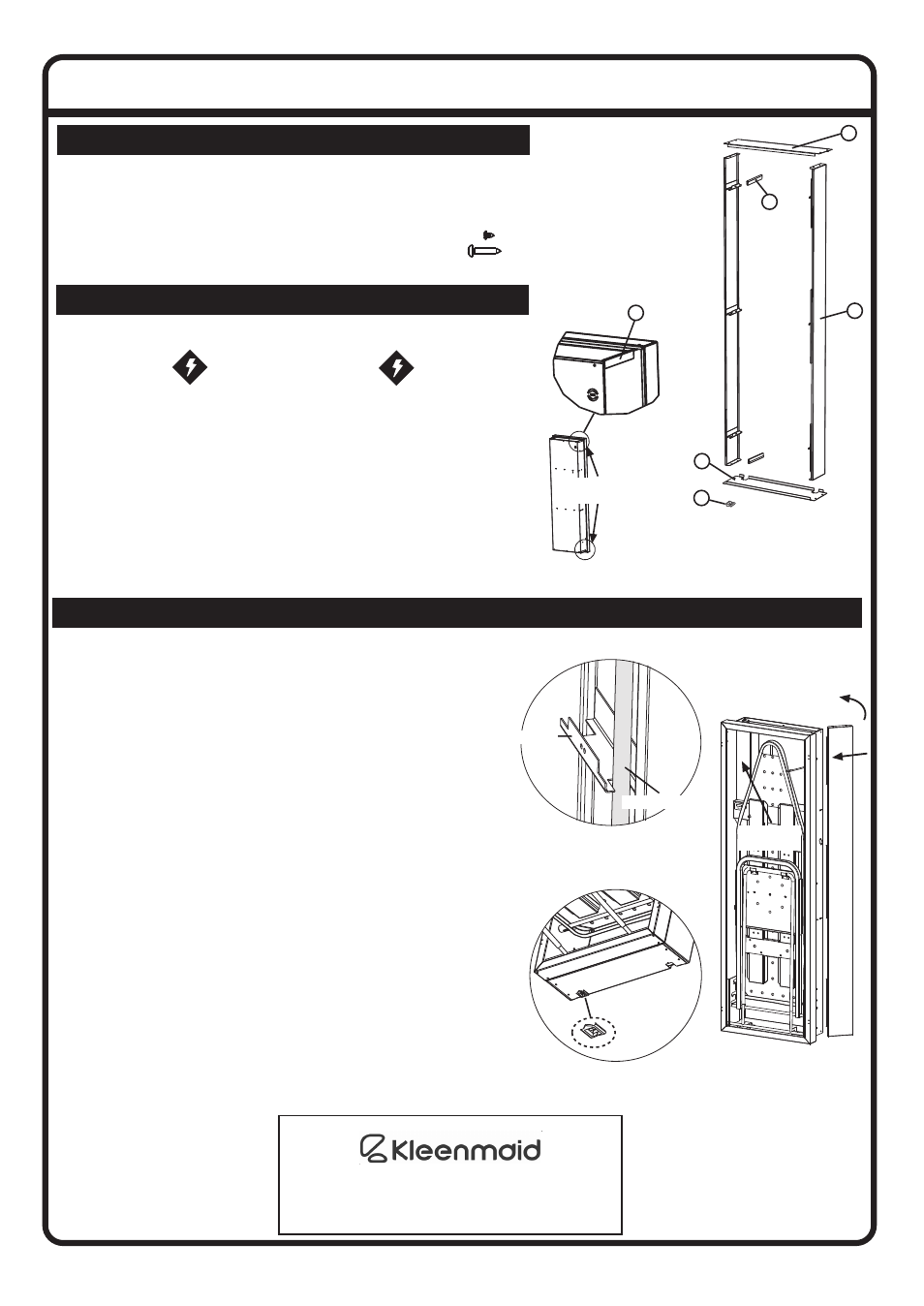
C O M P O N E N T S
The LWK330 Ironing Centre Collar is designed to fit a
surface mounted Ironing Centre.
Collar Kit contains:
(A) two Collar Sides.
(B) Collar Top.
(C) Collar Bottom.
P R E L I M E N A R Y I N S T R U C T I O N S
WARNING
THE TWO EDGE
COVERS (D) MUST BE INSTALLED TO THE
FLEXI-IRON BEFORE ASSEMBLING THE
COLLAR KIT TO PREVENT ELECTRICAL HAZARD.
• Clip the Edge Covers (D) into position (See dia. 1).
• Follow the Ironing Centre Installation Instructions to
mount the Ironing Centre to the wall.
Note: Please allow 100mm clear area on either
side of Ironing Centre for the Collar installation.
(Alternatively install the Collar to the Ironing Centre
before installing to the wall)
C O L L A R A S S E M B L Y
Note - this collar is interchangeable to allow the
powercord to exit at either the top or bottom of
the unit. Just swap part (B) with part (C) during
installation and take note of powercord route.
Instructions for fitting the collar with power
exiting at the bottom.
• Remove the wireway cover (dia. 3).
• Run the powercord through the brackets of the
Collar Side (A) (dia. 2).
• Position Collar Side (A) to the Flexi-Iron and swing
into place (dia. 3).
• Screw Collar Side (A) in place from inside using
three screws supplied (F).
• Repeat for second side.
• Place Collar Top (B) on top of unit and line up holes.
• Screw Collar Top (B) in place using four screws
supplied (E).
• Slide Edge Saddle (G) into Collar Bottom (C) to
protect the powercord (dia. 4).
• Pass the powercord through the Edge Saddle.
• Position Collar Bottom (C) in place on the bottom of
the ironing centre and align holes.
• Screw collar bottom (C) in place using four screws
supplied (E).
• Refit the Wireway Cover.
107844 issue “A”
ECN: 04053
RUN THE POWERCORD
THROUGH THE BRACKET
Bracket
Powercord
SWING CLOSED
COLLAR SIDE
Installation kit contains:
(D) two Edge Covers.
(E) eight Screws 6” x ¼”
(F) six Screws 8” x ¾”
(G) Edge Saddle
Edge Cover
Positions
C
A
B
D
Diagram 1.
Diagram 2.
Diagram 3.
EDGE SADDLE
POSITION
Diagram 4.
Edge Saddle
G
D
MANUFACTURED FOR:
BY:
ROBINHOOD LIMITED
6 ZELANIAN DRIVE, EAST TAMAKI
AUCKLAND, NEW ZEALAND
ISO9001 Certified
Wireway
Cover