Assembly, Operation – Koga E-BIKE BOSCH User Manual
Page 11
13
KOGA - BOSCH Active Line
Original instructions
English–2
Bosch eBike Systems
0 276 001 SAI | (14.8.13)
Indication Elements, HMI
a Motor-output indicator
b Assistance-level indicator
c Illumination indicator
d Text indication
e Value indication
f Speed indication
g Battery charge-control indicator
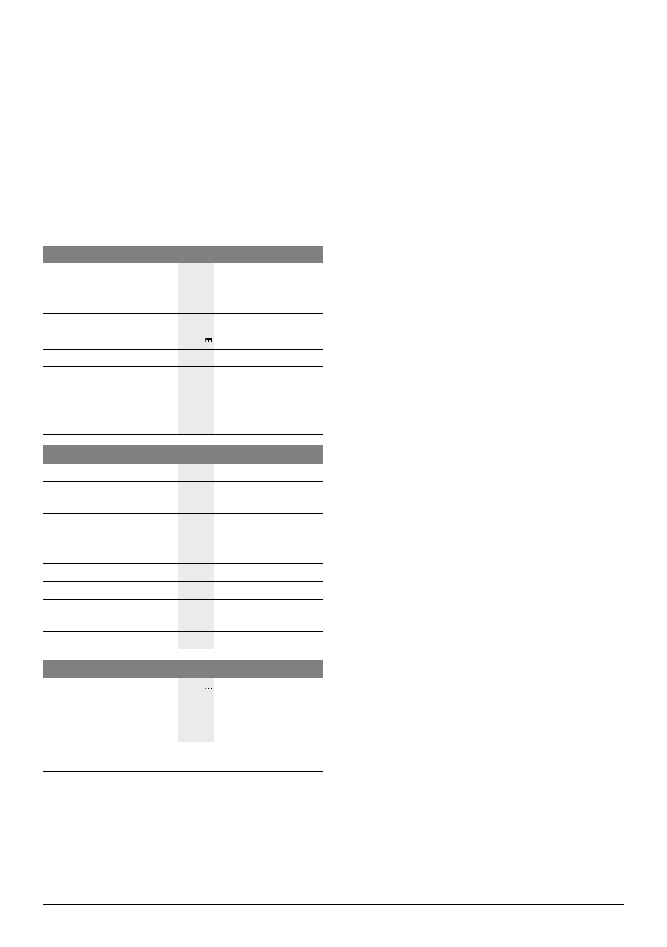
Technical Data
Assembly
Inserting and Removing the Battery Pack
For inserting and removing the battery pack in/from the eBike,
please read and observe the battery pack operating instruc-
tions.
Inserting and Removing the HMI (see figure A)
To insert the HMI 3, slide it from the front into the holder 4.
To remove the HMI 3, press the lock latch 15 and slide the
HMI toward the front out of the holder 4.
Remove the HMI when you park the eBike.
It is possible to secure the HMI against removal in the holder.
To do so, remove the holder 4 from the handlebars. Put the
HMI in the holder. Screw the locking screw 16 (thread M3,
8 mm long) from below into the thread provided in the holder.
Mount the holder back onto the handlebars.
Checking the Speed Sensor (see figure B)
The speed sensor 17 and its spoke magnet 18 must be
mounted in such a manner that the spoke magnet, after a turn
of the wheel, moves past the speed sensor with a clearance of
at least 5 mm, yet no more than 17 mm.
Note: If the clearance between speed sensor 17 and spoke
magnet 18 is too small or too large, or if the speed sensor 17
is not properly connected, the speed indication f will fail, and
the eBike drive will operate in emergency mode.
In this case, loosen the screw of the spoke magnet 18 and fas-
ten the spoke magnet to the spoke in such a manner that it
runs past the mark of the speed sensor at the correct clear-
ance. When the speed is still not being indicated in the speed
indication f after this, please refer to an authorised bicycle
dealer.
Operation
Initial Operation
Requirements
The eBike system can only be activated when the following
requirements are met:
– A sufficiently charged battery pack is inserted (see operat-
ing instructions of the battery pack).
– The HMI is properly inserted in the holder (see “Inserting
and Removing the HMI”, page English–2).
– The HMI is properly connected (see “Checking the Speed
Sensor”, page English–2).
Switching the eBike System On/Off
Options for switching on the eBike system:
– If the HMI is already switched on when inserted into the
holder, then the eBike system will be switched on automat-
ically.
– When the HMI and the battery pack are inserted, briefly
press the On/Off button 5 of the HMI once.
– When the HMI is inserted, press the On/Off button of the
battery pack (see battery pack operating instructions).
The drive is activated as soon as you step into the pedals (ex-
cept when in push-assistance mode, see “Switching the Push-
assistance mode On/Off”, page English–4). The motor out-
put depends on the settings of the HMI.
Drive Unit
Drive Unit
Article number
0 275 007 020
0 275 007 022
Rated continuous output
W
250
Torque at drive, max.
Nm
48
Rated voltage
V
36
Operating temperature
°C
–5...+40
Storage temperature
°C
–10...+50
Degree of protection
IP 54 (dust and splash
water protected)
Weight, approx.
kg
4
HMI
Intuvia
Article number
1 270 020 906
Max. charging current,
USB connection
mA
500
Charging voltage,
USB connection
V
5
Operating temperature
°C
–5...+40
Storage temperature
°C
–10...+50
Charging temperature
°C
0...+40
Degree of protection
IP 54 (dust and splash
water protected)
Weight, approx.
kg
0.15
Lighting*
Rated voltage
V
6
Power output
– Front light
– Rear light
W
W
6.6
0.6
* Not possible via the eBike battery pack in all country-specific versions,
depending on the statutory regulations
OBJ_BUCH-2074-001.book Page 2 Wednesday, August 14, 2013 12:19 PM