Lacava llc 4 – Lacava 1840 User Manual
Page 4
LACAVA LLC
4
Installation Instructions/Instrucciones de Instalación
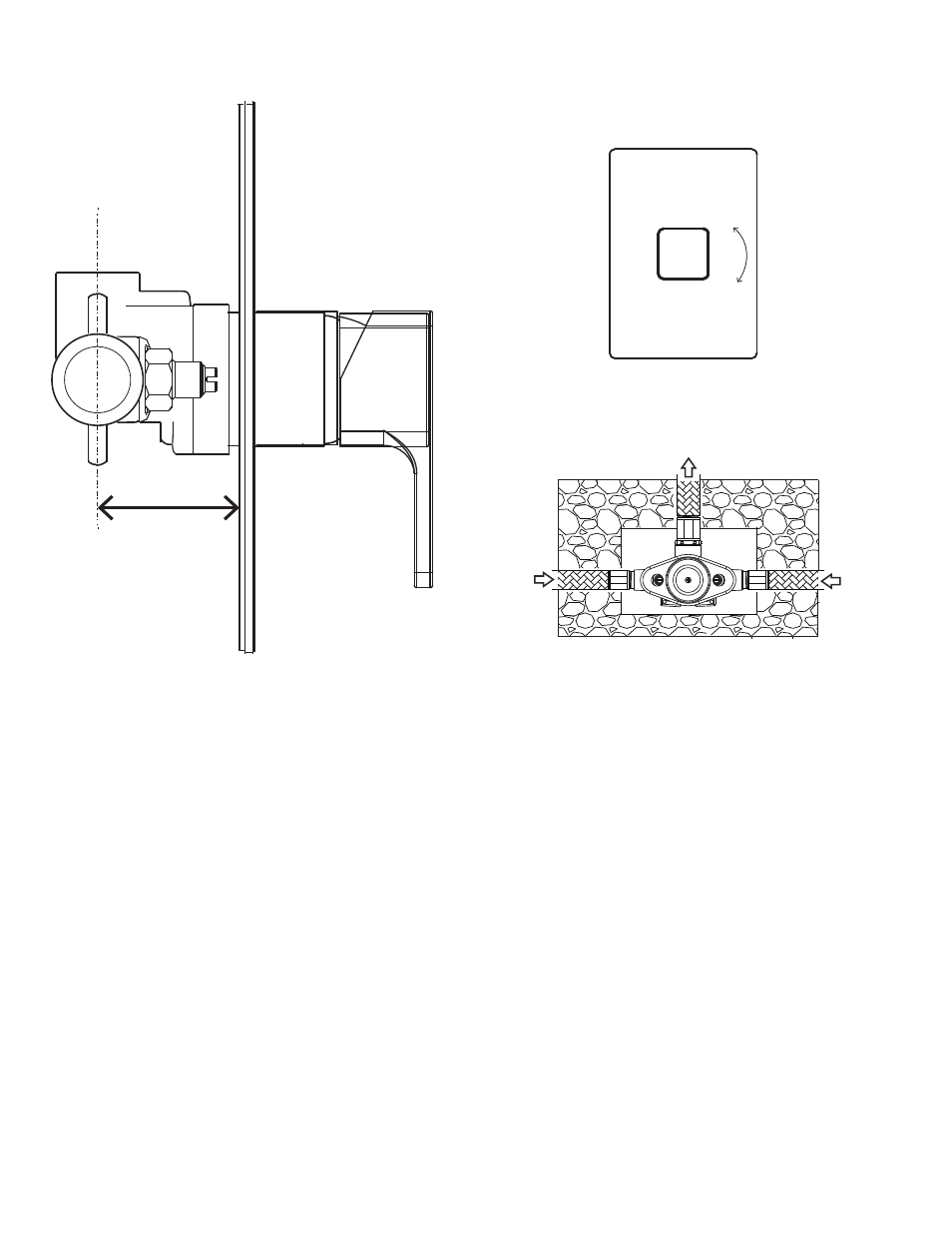
1. Determine the location of the valve. The distance from the center of the supply holes to the surface of the finished wall
must fall in the range: 2” - 2 1/2“ (see above).
2. Install support framing if needed and mount the valve using the provided screws.
3. Install 1/2” NPT threaded copper adapters to the outlet and hot & cold inlets Apply teflon tape to all threaded
connections. Then solder copper piping onto adapters and run to designated water supply and outlet.
Important! Take the following precautions if soldering copper piping directly onto valve:
a) Remove ALL components from the valve prior to soldering, including plaster guards, cartridge and service stops.
b) Wrap valve body with cold rag before soldering. Take special care not to overheat brass rough-in.
c) Use copper piping only, do not attempt to solder steel piping to valve.
d) Flush all pipes before reinstalling cartridge and service stops.
e) Reinstall all components after soldering.
4. Install 1/2” nipple to outlet so it extends beyond the finished wall and install a water-tight cap.
5. Turn on the hot and cold water supplies and check for any leaks.
6. Remove the plaster guard and make sure the valve is in the off position (turn stem clockwise). Remove outlet
cap and make sure to have a container set up to collect water. Open valve (turn stem counterclockwise) and
flush system.
7. Reinstall plaster guard and outlet cap.
H
C
outlet
50 - 65
2" - 2 1/2"
+
-
ON/OFF
TEMP.