LD Systems CONTRACTOR CFL 62 100 V User Manual
Page 11
11
1
TERMINAL CLAMPS FOR SPEAKER CABLES / KLEMMANSCHLÜSSE FÜR LAUTSPRECHERKABEL / BORNIERS À PINCES POUR CÂBLE
HAUT-PARLEUR / BORNES DE CONEXIÓN PARA EL CABLE DE ALTAVOZ / PRZYŁĄCZA ZACISKOWE DO KABLA GŁOŚNIKA /
ATTACCHI A MORSETTO PER CAVO ALTOPARLANTE
EN
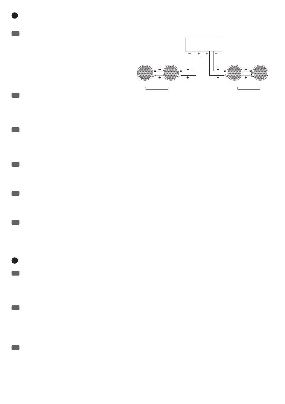
Connect the positive pole (+) of the speaker cable coming from
the amplifier to the red terminal clamp (+), and the negative pole (-) of
the speaker cable coming from the amplifier to the black terminal
clamp (-) (see figure A). When connecting multiple speakers in parallel
to a power amplifier, please be sure to have the same polarity,
minimum impedance (power amplifier) and total load (speakers). For
example: 2 speakers with 40 W of power and an impedance of 8
ohms each, when connected in parallel produce a total power of 80 W
and a total impedance of 4 ohms. Therefore, a channel of the power
amplifier with a power of at least 80 W at 4 ohms is required and
must therefore also be stable at 4 ohms.
DE
Verbinden Sie den Pluspol (+) des vom Verstärker kommenden
Lautsprecherkabels mit dem roten Klemmanschluss (+) und den Minuspol (-) des vom Verstärker kommenden Lautsprecherkabels mit dem
schwarzen Klemmanschluss (-) (siehe Abbildung A). Achten Sie beim parallelen Anschluss mehrerer Lautsprecher an einem Endstufenkanal auf
gleiche Polung, Mindestimpedanz (Endstufe) und Gesamtbelastbarkeit (Lautsprecher). Beispiel: 2 Lautsprecher mit je 40W Belastbarkeit und 8 Ohm
Impedanz parallel geschaltet ergeben eine Gesamtbelastbarkeit von 80W und eine Gesamtimpedanz von 4 Ohm. Ein Kanal der verwendeten Endstufe
muss also eine Leistung von mindestens 80W an 4 Ohm haben und demnach auch 4 Ohm stabil sein.
FR
Connectez le pôle Plus (+) du câble haut-parleur provenant de l'amplificateur au bornier rouge (+) et le pôle Moins (-) du câble haut-parleur
provenant de l'amplificateur au bornier noir (-) de l'enceinte – voir Figure A. En cas de branchement en parallèle de plusieurs enceintes sur un même
canal d'amplification, attention à bien respecter les polarités, l'impédance de charge minimale (côté amplificateur) et la puissance maximale
admissible (côté enceinte) Exemple : 2 enceintes, d'une puissance admissible de 40 Watts et d'une impédance de 8 Ohms, sont connectées en
parallèle : leur puissance admissible globale passe alors à 80 Watts et leur impédance résultante à 4 Ohms. Par conséquent, le canal d'amplification
correspondant doit lui aussi pouvoir fournir une puissance de 80 Watts sur 4 Ohms, et rester stable sur cette charge.
ES
Conecte el conductor positivo (+) del cable de altavoz procedente del amplificador al borne rojo (+), y el conductor negativo (−) del cable de
altavoz procedente del amplificador al borne negro (−) (Fig. A). Si se conectan varios altavoces en paralelo a un canal del amplificador, preste
atención a la polaridad, la impedancia mínima (amplificador) y la carga total (altavoces). Por ejemplo: si tenemos 2 altavoces, cada uno de 40 W de
potencia nominal y 8 ohmios de impedancia, al conectarlos en paralelo darán 80 W y presentarán una impedancia de 4 ohmios. Por lo tanto, el canal
del amplificador deberá tener una potencia mínima de 80 W sobre 4 ohmios, así que debe estar diseñado para 4 ohmios.
PL
Biegun dodatni (+) kabla głośnika wychodzącego ze wzmacniacza należy podłączyć do czerwonego przyłącza zaciskowego (+), a biegun
ujemny (-) kabla głośnika wychodzącego ze wzmacniacza do czarnego przyłącza zaciskowego (-) – patrz rys. A. Przy równoległym podłączaniu kilku
głośników do kanału końcówki mocy należy pamiętać o tym samym biegunie, oporze minimalnym (końcówka mocy) i obciążeniu łącznym (głośnik).
Przykład: podłączone równolegle 2 głośniki o obciążeniu 40 W i oporze 8 Ω każdy dają łączne obciążenie 80 W i łączny opór 4 Ω. Jeden kanał użytej
końcówki mocy musi mieć zatem moc co najmniej 80 W na 4 Ω i tym samym oferować stabilność dla 4 Ω.
IT
Collegare il polo positivo (+) del cavo dell'altoparlante proveniente dall'amplificatore all'attacco rosso a morsetto (+) e il polo negativo (−) del
cavo dell'altoparlante proveniente dall'amplificatore all'attacco nero a morsetto (−) (v. Figura A). Quando si collegano in parallelo diversi altoparlanti a
un canale del finale di potenza, verificare che abbiano la stessa polarità, impedenza minima (finale di potenza) e potenza complessiva (altoparlanti).
Esempio: due altoparlanti, con 40 W di potenza nominale ciascuno e 8 ohm di impedenza, attivati in parallelo emettono una potenza complessiva di
80 W e avranno un'impedenza complessiva di 4 ohm. Anche un canale del finale di potenza utilizzato deve avere una potenza minima di 80 W su
4 ohm; pertanto deve essere compatibile per 4 ohm.
2
MOUNTING CLAMPS / MONTAGEKLEMMEN / FIXATIONS DE MONTAGE / PESTAÑAS DE MONTAJE / ZACISKI MONTAŻOWE /
MORSETTI DI MONTAGGIO
EN
4 mounting clamps per speaker ensure a safe installation in the wall material (material thickness 3 - 15 mm). To install the speaker in a wall,
the speaker front grille must first be removed. For this purpose, use the supplied hook and take care to ensure that the mounting clamps are turned
inward towards the speaker magnet in the default position. Place the speaker in the wall cavity (cut-out size LDCFL52 = Ø 178 mm / LDCFL62 = Ø
210 mm, templates included), press it gently against the edge of the cut-out and rotate the fastening screws of the mounting clamps clockwise in
the outer ring of the speaker using an appropriate screwdriver. The mounting clamps automatically click into the correct mounting position towards
the outside. Ensure a tight fit for the speaker. Place the front grille onto the speaker; the integrated magnets provide a firm support.
DE
4 Montageklemmen je Lautsprecher gewährleisten sicheren Halt im Wandmaterial (Materialstärke 3 - 15 mm). Um den Lautsprecher in einer
Wand einzubauen, muss das Frontgitter vom Lautsprecher entfernt werden. Verwenden Sie hierfür den mitgelieferten Haken und achten darauf, dass
die Montageklemmen in die Grundposition nach innen Richtung Lautsprechermagnet gedreht sind. Setzen Sie den Lautsprecher in den Wandaus-
schnitt (Ausschnittgröße LDCFL52 = Ø 178 mm / LDCFL62 = Ø 210 mm, Schablonen im Lieferumfang), drücken ihn leicht gegen den Ausschnittrand
und drehen die Befestigungsschrauben der Montageklemmen im äußeren Ring des Lautsprechers mit einem geeigneten Schraubendreher im
Uhrzeigersinn fest. Die Montageklemmen klappen sich dabei automatisch nach außen in die korrekte Montageposition. Achten Sie auf festen Halt
des Lautsprechers. Setzen Sie das Frontgitter auf den Lautsprecher, im Rahmen integrierte Magnete sorgen für sicheren Halt.
FR
4 fixations de montage par enceinte garantissent une tenue sûre dans la paroi murale (épaisseur du matériau : de 3 à 15 mm). Pour encastrer
l'enceinte dans un mur, il faut d'abord démonter sa grille frontale. Pour ce faire, utilisez le crochet livré, et veillez à ce que les fixations de montage
sont tournées en position de base, vers l'intérieur (direction de l'aimant du haut-parleur). Placez l'enceinte dans la découpe du plafond (dimensions :
LDCFL52 = Ø 178 mm / LDCFL62 = Ø 210 mm, gabarits livrés), appuyez-la doucement contre les bords, et tournez dans le sens des aiguilles d'une
montre les vis des fixations de l'enceinte (bord extérieur) avec un tournevis adapté. Les fixations de montage s'enclenchent automatiquement depuis
l'extérieur en position correcte de montage. Vérifiez que l'enceinte tient bien en place. Placez la grille avant sur l'enceinte : des aimants intégrés au
châssis assurent un maintien sûr.
8Ω
8Ω
8Ω
8Ω
RIGHT
LEFT
AMPLIFIER 2 X 80 W @ 4 OHMS
4Ω Total impedance
4Ω Total impedance