Ul certification – Legrand FS User Manual
Page 2
2
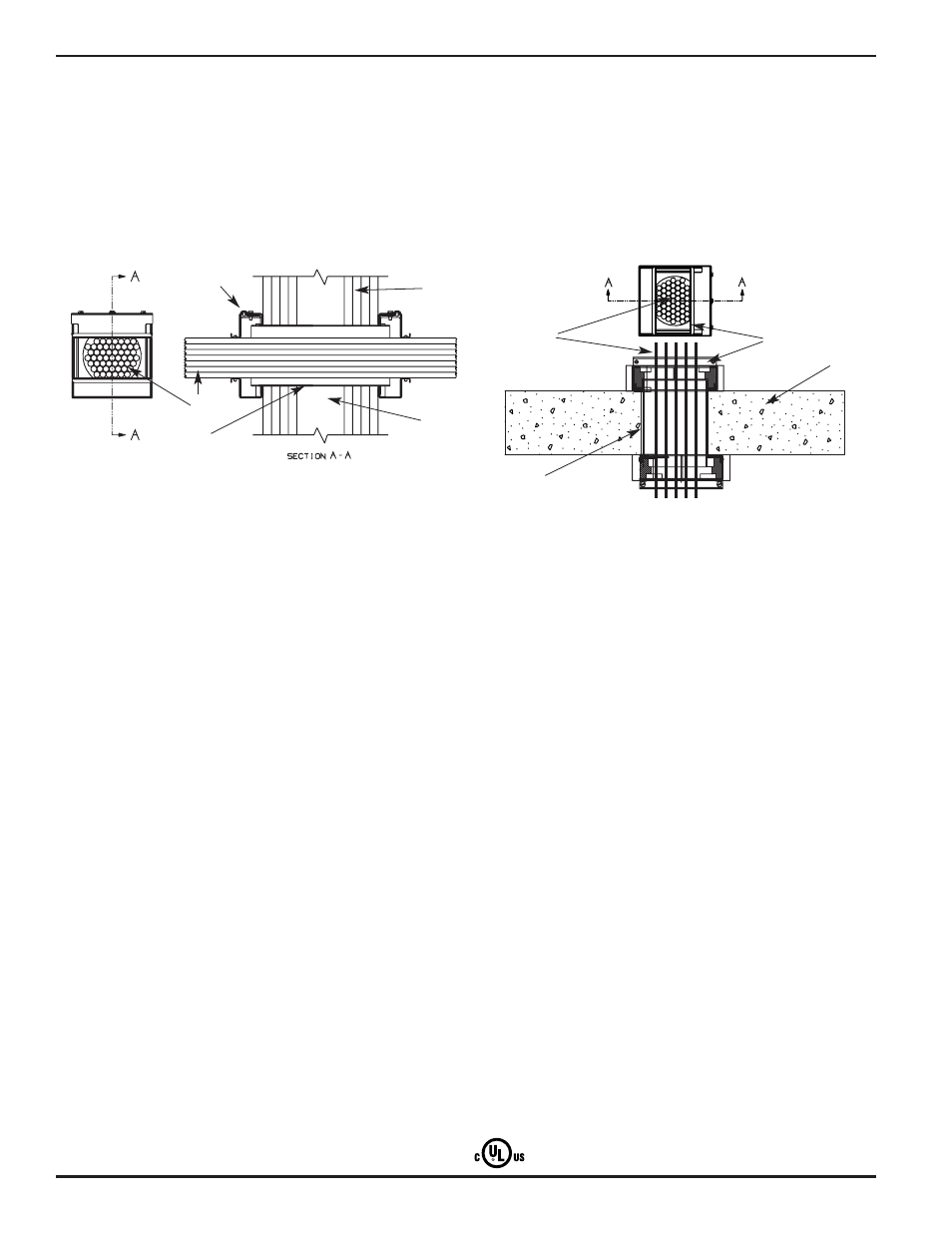
1. Wall Assembly – The 1, 2, 3 or 4 hr fire-rated gypsum board/stud wall assembly shall
be constructed of the materials and in the manner described within the individual U300,
U400 or V400 Series Wall or Partition Designs in the UL Fire Resistance Directory and
shall incorporate the following construction features:
A. Studs – Wall framing shall consist of either wood studs or steel channel studs. Wood
studs to consist of nom 2 by 4 in. [51 by 102 mm] lumber spaced max 16 in. [406 mm]
OC. Steel studs to be min 1-5/8 in. [41 mm] wide and spaced max 24 in. [610 mm] OC.
B. Gypsum Board* – Thickness, type, number of layers and fasteners as specified in the
individual Wall and Partition Design. Diam of opening shall be 2-1/4 in. [57 mm] and 4-3/4 in.
[121 mm] for the nom 2 in. [51 mm] and 4 in. [102 mm] sleeves (Item 2), respectively.
The hourly F Rating of the firestop system is dependent upon the hourly rating of the
wall in which it is installed.
2. Metallic Sleeve – Nom 2 in. [51 mm] or 4 in. [102 mm] diam electrical metallic tubing
(EMT), dependent on the size of the firestop device (Item 4). The sleeve is to extend a nom
3/4 in. beyond both surfaces of wall. The annular space between the sleeve and the
periphery of opening shall be min 0 in. (continuous point contact) to max 1/4 in. [6 mm].
3. Cables – Aggregate cross-sectional area of cables in the EMT sleeve to be 0% to max
60% of the aggregate cross-sectional area of the EMT sleeve. When there is no cable fill,
device cover is to be tightly closed. Cables to be rigidly supported on both sides of the
wall assembly. Any combination of the following types of cables may be used:
A. Single conductor No. 18 AWG (or smaller) RG/U coaxial cable with fluorinated
ethylene insulation and jacketing.
B. Fiber optic cable with polyvinyl chloride (PVC) or polyethylene (PE) jacket and
insulation having a max diameter of 5/8 in. [16 mm].
C. Max 4 pair No. 22 AWG (or smaller) copper conductor data cable with polyvinyl
chloride (PVC) or plenum rated jacketing and insulation.
D. Max 4/C No. 2 AWG (or smaller) copper conductor cable with XLPE/PVX insulation
and PVC jacket.
E. Max 100 pair No. 24 AWG (or smaller) copper conductor telecommunication cable
with polyvinyl chloride (PVC) jacketing and insulation.
F. Max 400 pair No. 24 AWG (or smaller) copper conductor telecommunication cable
with polyvinyl chloride (PVC) jacketing and insulation.
G. Max 8/C 12 AWG (or smaller) copper conductor steel Metal-Clad or Armored-Clad cable.
The hourly T Rating of the firestop system is equal to the F Rating when no cable fill is used
or when cables A or B are used. The hourly T Rating is equal to the F Rating up to 3 hr when
cable C is used. The hourly T Rating is 1 hr when cable D is installed in 2, 3 or 4 hr rated
walls, 1/2 hr in 1 hr rated walls. The hourly T Rating is 1 hr when cable E is installed in 4 hr
rated walls and 0 hr in 1, 2 or 3 hr rated walls. The hourly T Rating is 3/4 hr when cable F is
installed in 2, 3 or 4 hr rated walls, 0 hr in 1 hr rated walls. The hourly T Rating is 1/4 hr
when cable G is installed in 2, 3 or 4 hr rated walls, 0 hr in 1 hr rated walls.
The L Rating at ambient and 400°F with no cable fill is 2.6 CFM and 1.9 CFM, respectively.
The L Rating at ambient and 400°F with cable fill is 2.8 CFM and 1.3 CFM, respectively.
4. Firestop Device – Device to be installed in accordance with the accompanying installation
instructions. Device to be installed and secured to the EMT sleeve both sides of wall.
THE WIREMOLD COMPANY – FS2R FlameStopper, FS4R FlameStopper
*Bearing the UL Classification Mark
1. Floor & Wall Assembly – Min 4-1/2 in. [114 mm] thick reinforced lightweight or normal
weight (100-150 pcf or 1600-2400 kg/m3) concrete floor or wall. Wall may also
be constructed of any UL Classified Concrete Blocks*. Maximum diameter of opening is
4-1/2 in. [114 mm].
See Concrete Blocks (CAZT) category in the Fire Resistance Directory for names of manufacturers.
*4-Hour Rated Assemblies (System No. W-J-3154): for concrete wall installation, minimum
6 in. [152mm] thick, reinforced lightweight or normal weight (100-150 pcf or 1600-2400
kg/m3) concrete wall.
2. Metallic Sleeve – Nom 2 in. [51 mm] or 4 in. [102 mm] diameter electrical metallic tubing
(EMT), dependent on the size of the firestop device (Item 4). The sleeve is to extend a nom
5/8 in. [16mm] beyond both surfaces of floor or wall. The annular space between the sleeve
and the periphery of opening shall be min 0 in. (continuous point contact) to max 1/4 in.
[6 mm].
3. Cables – Aggregate cross-sectional area of cables in the EMT sleeve to be 0% to max 60%
of the aggregate cross-sectional area of the EMT sleeve. When there is no cable fill, device
cover is to be tightly closed. Cables to be rigidly supported on both sides of the wall
assembly. Any combination of the following types of cables may be used:
A. Single conductor No. 18 AWG (or smaller) RG/U coaxial cable with fluorinated ethylene
insulation and jacketing.
B. Fiber optic cable with polyvinyl chloride (PVC) or polyethylene (PE) jacket and insulation
having a max diameter of 5/8 in. [16 mm].
C. Max 4 pair No. 22 AWG (or smaller) copper conductor data cable with polyvinyl chloride
(PVC) or plenum rated jacketing and insulation.
D. Max 4/C No. 2 AWG (or smaller) copper conductor cable with XLPE/PVX insulation and
PVC jacket.
E. Max 100 pair No. 24 AWG (or smaller) copper conductor telecommunication cable with
polyvinyl chloride (PVC) jacketing and insulation.
F. Max 400 pair No. 24 AWG (or smaller) copper conductor telecommunication cable with
polyvinyl chloride (PVC) jacketing and insulation.
G. Max 8/C 12 AWG (or smaller) copper conductor steel Metal-Clad or Armored-Clad cable.
The hourly T Rating is 3 hr when no cable fill is used or when cables A, B or C are used. The
hourly T Rating is 3/4 hr when cable D is used. the hourly T Rating is 1 hr when cables E
and F are used. The hourly T Rating is 1/4 hr when cable G is used.
4. Firestop Device – Device to be installed in accordance with the accompanying installation
instructions. Device to be installed and secured to the EMT sleeve both sides of wall
or floor.
THE WIREMOLD COMPANY – FS2R FlameStopper, FS4R FlameStopper
*Bearing the UL Classification Mark
u
UL Certification
From UL Fire Resistance Directory
Through-penetration Firestop Systems
System No. W-L-3300
December 28, 2005
Ratings – 1, 2, 3 and 4 Hr (See Item 1)
T Ratings – 0, 1/4, 1/2, 3/4, 1, 2, 3, and 4 Hr (See Item 3)
L Rating at Ambient – 2.6 CFM and 2.8 CFM (See Item 3)
L Rating at 400°F – 1.9 CFM and 1.3 CFM (See Item 3)
Through-penetration Firestop Systems
System No. C-AJ-3271
January 12, 2006
F Rating – 3 Hr*
T Ratings – 1/4, 3/4, 1, & 3 (See Item 3)
L Rating at Ambient – 2.6 CFM and 2.8 CFM (See Item 3)
L Rating at 400°F – 1.9 CFM and 1.3 CFM (See Item 3)
FIRESTOP DEVICE FOR USE IN THROUGH-PENETRATION
FIRESTOP SYSTEMS. SEE UL DIRECTORY OF PRODUCTS
CERTIFIED FOR CANADA AND UL FIRE RESISTANCE DIRECTORY
D
E
I
F
I
S
S
A
L
C
1A
3
2
1B
4
3
2
1
4