Ul certification – Legrand FS User Manual
Page 7
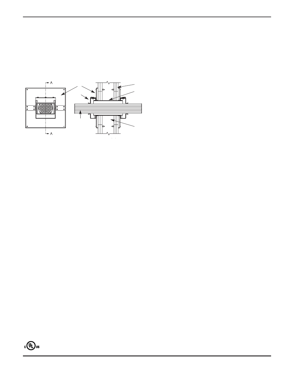
1. Wall Assembly – The 1 or 2 hr fire-rated gypsum board/stud wall assembly shall be
constructed of the materials and in the manner described within the individual U300, U400
or V400 Series Wall or Partition Designs in the UL Fire Resistance Directory and shall
incorporate the following construction features:
A. Studs – Wall framing shall consist of either wood studs or steel channel studs. Wood
studs to consist of nom 2 by 4 in. [51 by 102 mm] lumber spaced max 16 in. [406 mm]
OC. Steel studs to be min 2-1/2 in. [64 mm] wide and spaced max 24 in. [610 mm] OC.
B. Gypsum Board* – Thickness, type, number of layers and fasteners as specified in the
individual Wall and Partition Design. Max area of opening shall be 100 sq in. [645 sq
cm] with a max dimension of 10 in. [254 mm] for the FS4RWP12 device (Item 3B).
Max area of opening shall be 36 sq in. [232 sq cm] with a max dimension of 6 in.
[152 mm] for the FS4RWP12 device (Item 3B).
The hourly F Rating of the firestop system is dependent upon the hourly rating of the
wall in which it is installed.
2. Cables – Aggregate cross-sectional area of cables in the EMT sleeve to be 0% to max 60%
of the aggregate cross-sectional area of the EMT sleeve. When there is no cable fill, device
cover is to be tightly closed. Cables to be rigidly supported on both sides of the wall
assembly. Any combination of the following types of cables may be used:
A. Max 4 pair No. 22 AWG (or smaller) copper conductor data cable with polyvinyl chloride
(PVC) or plenum rated jacketing and insulation.
B. Single conductor No. 18 AWG (or smaller) RG/U coaxial cable with fluorinated ethylene
insulation and jacketing.
C. Fiber optic cable with polyvinyl chloride (PVC) or polyethylene (PE) jacket and insulation
having a max diameter of 5/8 in. (16 mm).
D. Max 8/C 12 AWG (or smaller) copper conductor steel Metal-Clad or Armored-Clad cable.
The hourly T Rating of the firestop system is 1-1/4 hr when no cable fill is used or when
cables A or C are used in 2 hr rated walls, 1/2 hr in 1 hr rated walls. The hourly T Rating is
1 hr when cable B is installed in 2 hr rated walls, 1/2 hr in 1 hr rated walls. The hourly T
Rating is 1/4 hr when cable D is installed in 2 hr rated walls, 0 hr in 1 hr rated walls.
The L Rating at ambient and 400°F with no cable fill is 1.7 CFM and 1.8 CFM, respectively.
The L Rating at ambient and 400°F with cable fill is 3.3 CFM and 2.0 CFM, respectively.
3. Firestop System – The firestop system shall consist of the following:
A. Sleeve – The octagonal, two-piece, 16 gauge (or heavier) galv steel sleeve shall be
installed in accordance with the accompanying installation instructions.
B. Firestop Device* – Wall Covering Plate – The two-piece wall covering plates shall be
installed on both sides of wall in accordance with the accompanying installation
instructions. The plates shall overlap opening a min 1 in. [25 mm] on all sides. The
plates are secured around sleeve and attached to gypsum board with min 1/8 in. [3.2
mm] diam steel toggle bolts. A min 16 gauge, 2-3/4 by 1-1/2 in. [70 by 38 mm] galv
steel plate is secured to the steel plates over the seams between top and bottom plates
with min No. 14 steel sheet metal screws.
THE WIREMOLD CO. – FS2RWP8, FS4RWP12
C. Firestop Device* – Device to be installed in accordance with the accompanying
installation instructions. Device to be installed and secured to the steel sleeve (Item
3A) on both sides of wall.
THE WIREMOLD CO. - FS2R FlameStopper, FS4R FlameStopper
*Bearing the UL Classification Mark
7
u
UL Certification
From UL Fire Resistance Directory
Through-penetration Firestop Systems
System No. W-L-3302
December 28, 2005
F Ratings – 1, and 2 Hr (See Item 1)
T Ratings – 0, 1/4, 1/2, 1 and 1-1/4 Hr (See Item 3)
L Rating at Ambient – 1.7 CFM and 3.3 CFM (See Item 3)
L Rating at 400°F – 1.8 CFM and 2.0 CFM (See Item 3)
FIRESTOP DEVICE FOR USE IN THROUGH-PENETRATION
FIRESTOP SYSTEMS. SEE UL DIRECTORY OF PRODUCTS
CERTIFIED FOR CANADA AND UL FIRE RESISTANCE DIRECTORY
D
E
I
F
I
S
S
A
L
C
3B
3C
2
1A
1B
3A