Legrand RFB Series Floor Boxes User Manual
Page 3
3
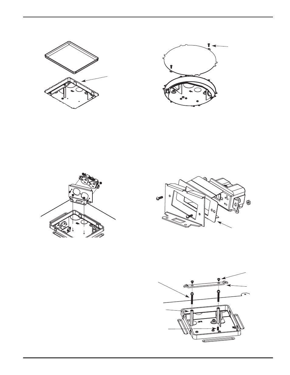
Step 9. Remove mud cap from box and clean out any
debris from inside of box.
Chip out concrete and
lift out Mud Cap
Remove two (2) #8 Screws
securing the steel plate
Mud Cap
RFB6 Mud Cap Removal
RFB4E & RFB6E Mud Cap Removal
RFB6 Series – Chip away concrete located in mud cap and
remove. If concrete does not break cleanly around preset,
the activation might not be properly supported. The
concrete edges around the top opening of the installed
box must be smooth and level for the proper fit of the
FloorPort Activations.
RFB4E & RFB6E Series – Remove the two (2) #8 screws
securing the stell plate mud cap.
Step 10. Wire devices (not supplied by Wiremold) in accordance to the NEC and any local codes. Mount
devices to device plates as shown. Lower device plate into floor box and slide back into position.
Secure device plate to floor box base with two (2) #8-32 mounting screws pre-installed in base of box.
Secure the receptacle to the receptacle device plate with
two (2) screws and nuts. Attach the receptacle device
plate(s) to the base with the two (2) #8-32 mounting
screws provided.
NOTE: Use insulator as shown with Cat. No. RFB6GFI.
Insulator placed between
GFI and Device Plate
Step 11. (RFB6 only for use with FloorPort
TM
Series
Activations) Attach cover mounting hardware
provided in hardware bag supplied with floor box.
Thread #10-24 x 2 in. hex standoff onto stud
projecting upward from floor box base. Insert two
(2) threaded adjusting screws into standoffs and
place link strap over head of threaded adjusting
screws. Secure link strap to threaded adjusting
screws with two (2) #8-32 x 3/16 in. screws.
Complete installation of cover following directions
provided with FloorPort
TM
Series Activation
Instruction Sheet 1008150.
#8-32 x 3/16"
Link Strap
#10-24 Threaded
Adjusting Screw
#10-24 x 2"
hex standoff
#10-24 x 2"
Stud