Legrand AV3 User Manual
Page 2
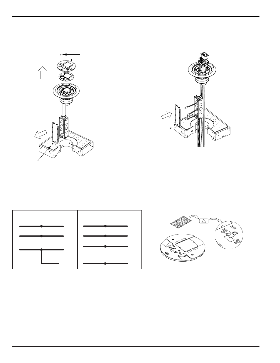
CONVENTIONAL WIRING SCHEMATIC
ISOLATED GROUND WIRING SCHEMATIC
BLACK or HOT
BLACK
BLACK or HOT
BLACK
From branch circuit
from Poke-Thru receptacle From branch circuit
from Poke-Thru receptacle
WHITE or NEUTRAL WHITE
WHITE or NEUTRAL WHITE
From branch circuit
from Poke-Thru receptacle From branch circuit
from Poke-Thru receptacle
GREEN or GROUND GREEN
ISOLATED GROUND GREEN
From branch circuit
from Poke-Thru receptacle From branch circuit
from Poke-Thru receptacle
System Ground
GREEN or GROUND GREEN
(jumper wire)
From branch circuit
from Poke-Thru
System Ground
junction box
GREEN (jumper wire)
from Poke-Thru
junction box
WARNING: Ground wire from junction box must be connected to system ground.
2
Slide Cover
Mounting Screws
Two (2) #6-32
Outlet Box
Cover Plate Screw
Complete Assembly:
Step 6
Wire the Poke-Thru device. (Can be
completed above floor.) Refer to
wiring schematic in Step 8.
Step 7
Wire the POWER and Communications
circuits. (See Steps 10 & 11 for
Communication Selection)
CAUTION: Poke-Thru can not be rotated in hole after
inserted into the floor.
NOTE: Electrical and communication
cables may be connected to unit
prior to or after activation.
NOTE: Factory supplied junction box shown. Junction
boxes must be located in an accessible location.
Poke-Thru devices with an "LJB" or "LJB25"
suffix are supplied without a junction box (sup-
plied by others).
CAUTION: Receptacle mounting means not grounded. Grounding
wire connection required. For isolated ground wiring,
connect ground leads to a separate isolated
grounding conductor. See NEC 250-146(d).
NOTE: The orange triangle shall only be placed on
devices that are wired for isolated ground.
See NEC 250-146(d).
Step 8
Connect Poke-Thru conductors according
to required device configuration. See
schematic below.
Step 9
If circuit is connected to an isolated ground,
apply IG icon on receptacle slide as shown.