Legrand RC3 Replacement Scrub Water Cover Assembly Kit User Manual
Page 3
3
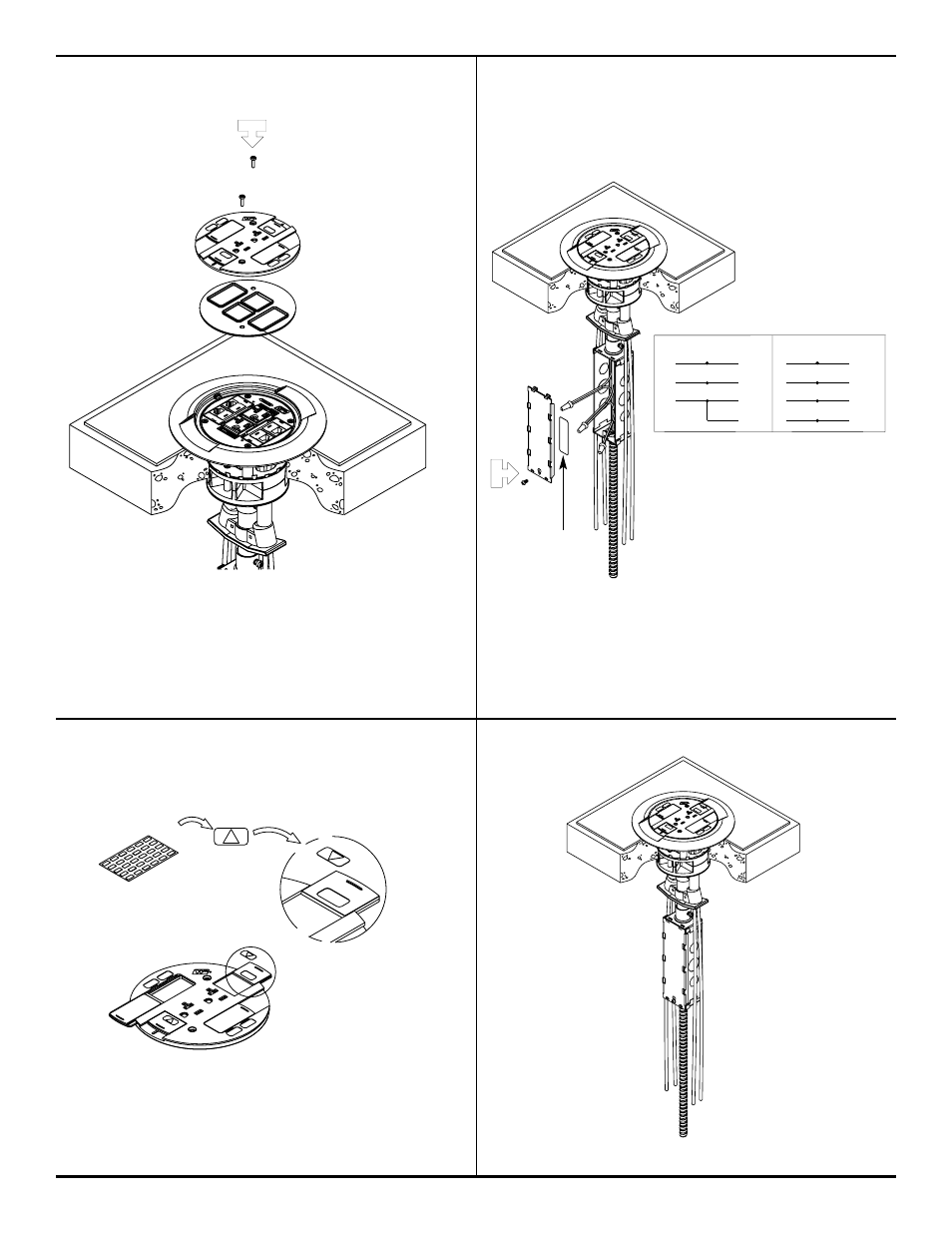
Step 9. Attach internal gasket and slide
Step 10. Stick wiring label on the inside of the
holder assembly.
junction box cover. Reattach receptacle
wires and junction box cover. Connect
Poke-Thru conductors according to required
device configuration (see schematic below).
CAUTION: Receptacle mounting means not
grounded. Grounding wire
connection required. For
isolated ground wiring,
connect ground leads
to a separate isolated
grounding conductor.
See NEC250-146(d).
CAUTION: Gasket must be set in place to provide
scrub water seal.
CAUTION: Do not over tighten cover mounting screws.
Step 11. If circuit is connected to an isolated
Step 8. Completed installation.
ground, apply IG icon on receptacle
slide as shown.
NOTE: The orange triangle shall only be placed on devices
that are wired for isolated ground. See NEC 250-146(d).
WHITE or NEUTRAL
from branch circuit
WHITE
from poke-thru receptacle
BLACK or HOT
from branch circuit
BLACK
from poke-thru receptacle
GREEN (jumper wire)
from poke- thru junction box
GREEN
from poke-thru receptacle
CONVENTIONAL WIRING SCHEMATIC
WHITE or NEUTRAL
from branch circuit
WHITE
from poke-thru receptacle
BLACK or HOT
from branch circuit
BLACK
from poke-thru receptacle
GREEN (jumper wire)
from poke-thru junction box
ISOLATED GROUND
from branch circuit
GREEN
from poke-thru receptacle
ISOLATED GROUND WIRING SCHEMATIC
GREEN or GROUND
from branch circuit
SYSTEM GROUND
GREEN or GROUND
from branch circuit
SYSTEM GROUND
WARNING:
Ground wire from junction box must be connected to SYSTEM GROUND.
Wiring Label