Legrand VA Trenchduct Flush Floor Feeder System User Manual
Page 2
4. Height Adjustment:
A. The height adjustment of the trenchduct system is -0" + 5/8". Secure all trench components prior to making adjustments.
Be certain that the trench base will rest on a solid surface or that concrete will be installed under the trench base
so that partitions and support studs will effectively support cover plates.
B. Field install leveling screws only where required. Trenchduct should be set to screed using a laser, and is not adjustable
after the concrete pour.
C. Full bottom VA trench can be adjusted two ways:
1. The entire trench assembly can be adjusted as a unit using the height adjusting screw on the leveling foot. Do not
loosen the set screw on the combination clip. Install one additional set screw into the combination clip and engage the
metal rib to help support the trench bottom pan. The setscrew is a #8-32 x 1/4" self-threading, Taptite brand screw. It is
Walker part #429071-016. Additional screws are shipped separately or packed in a hardware bag with the leveling feet.
2. To raise the aluminum rail and cover assembly only, secure the trench bodies to the form or sub-slab. Loosen and/or
remove the set screw and turn the adjusting screw as required. After leveling is complete, tighten the two combination
clip fastening screws.
5. Final Review and Adjustments:
A.. Inspect all components for gaps or openings where concrete mix may enter the system. Secure these openings with
waterproof sealing compound (Walker part# 290G) or duct tape (Walker part # H296).
B. Witness and check the concrete pour to be certain that the concrete is flush with the top of the cover plate. Refer to
Finishing Notes and Details.
C. After the concrete pour, any partitions shall be adjusted so they bear against the underside of the cover plates when the
final cover leveling is completed. Weld the partitions together with 1/8" [3.2mm] x 1/2" [12.7mm] long fillet welds at each
end and on two foot centers. Paint the welds with a corrosion resistant paint. Clear all debris and deburr any sharp edges
that would interfere with wiring.
D.
Any support studs shall be adjusted so they bear against the underside of the cover plate.
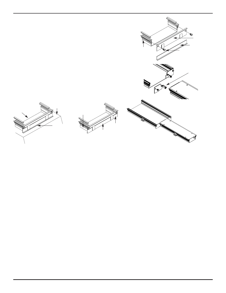
3. End Closure:
A. For full length closure, fasten top part of end closure to
end of trenchduct with two hex head screws provided
(see Figure 1). For partial end closure, fasten closure to
end of wider trenchduct with hex head screws provided
(see Figure 2).
B. Tighten screws into aluminum rail slot until end closure is
secure to trenchduct.
C. For partial closure, slide twin pilot into aluminum rail of
narrow trenchduct and tighten #10-24 hex head screws
(see Figure 2A).
D. Install and adjust bottom part of end closure (maximum 1"
[25mm]) until it is level with bottom of trenchduct.
E. If used on cell or deck, tack weld end closure bottom
flange to top of raceway (see Figure 3).
F. If used on underfloor duct or alone, flip end closure
bottom around so bottom flange is hidden under
trenchduct (see Figure 4).
Top Part
Bottom Part
Trenchduct
Figure 1
Figure 2
Figure 2A
Figure 4
Figure 3
Hex Head Screw
Twin pilot
Top of Raceway
Trenchduct
Tack Weld
Along Here
Bottom Part
(Flip Over)
Top Part
Trenchduct