Instructions to install on n-r-g presets, Instructions to install on flushduct, N-r-g series – Legrand Multiplex Series Multi-Service Pedestal Service Fittings User Manual
Page 2
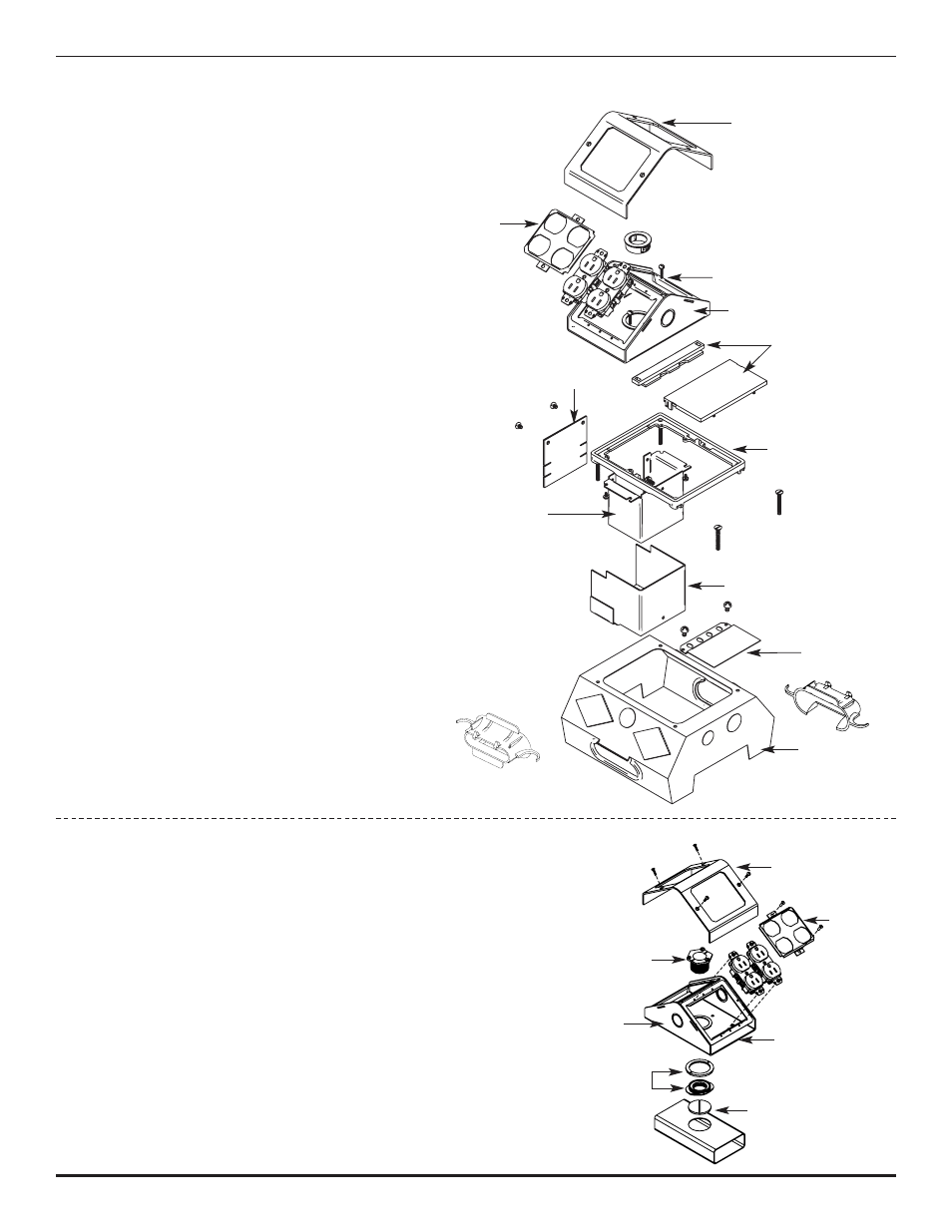
Instructions to Install on N-R-G Presets:
1. Install closure plate over unused opening,
if needed.
2. Snap communication cell grommets in
place (refer to instruction sheet 1 000 081).
3. Install power barrier base over other power
opening in preset. Tighten down to top of
power cell with two machine screws.
4. Install power barrier base over other power
opening in preset. Tighten down to top of
power cell with two machine screws.
5. Attach power barrier top sleeve to underneath
side of leveling ring with two #8-32 screws.
6. Attach power barrier closure (field modify height,
if required) to top sleeve with two #10-16 screws.
7. Install ground wire between power barrier top
sleeve and base. Slide top sleeve/leveling ring
down into enclosure.
8. Install leveling ring so that top surface will
be approximately 1/16" [1.6mm] below top
of carpet. Install access covers (M4 only).
Attach base of fitting to leveling ring so that
base is tight against both carpet and ring.
9. Install round grommet and mounting
frame into base. Install partition to
separate services, if needed (MP8 size only).
10. Install UL Listed wiring devices and/or
communication services. Cut off excess
length on electrical device mounting screw
(top screws only). Attach faceplates over
each opening and screw on cover.
Instructions to Install on Flushduct:
1. Cut carpet opening to expose plug in the flushduct.
Unscrew and remove plug. Drop bottom part of
outlet flange into flushduct and screw on top part.
2. Put electrical conductors and/or communication cables
thru opening(s). Route cables thru opening in base of
multiplex and thru locking nipple. Position the multiplex
base and secure in place by threading the locking nip-
ple into the outlet flange in the duct. Tighten screws in
locking nipple to hold in place. Install partition, if need-
ed, to separate services (MP8 size only).
3. Attach mounting frames into place and install UL
Listed wiring devices in accordance with the National
Electrical Code or any other local codes that apply.
Make sure that any ground leads are connected to
ground screws. Attach faceplates and cover with
screws provided.
Cover
Faceplate
Locking Nipple
Base
Outlet Flange
Mounting Frame
Flushduct Plug
Base
Leveling
Ring
Access Cover
Power Barrier Closure
Power Barrier
Top Sleeve
Power Barrier Base
Communications Grommet
Closure Plate
Faceplate
Mounting Frame
N-R-G Series
Cover
N-R-G Preset