Install on 2" [51mm] ips presets or aftersets, Instructions to install on, Walkerduct pro series preset – Legrand Multiplex Series Multi-Service Pedestal Service Fittings User Manual
Page 3
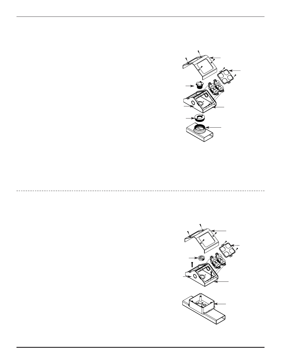
Install on 2" [51mm] IPS Presets or Aftersets
:
1. Determine location of insert using any of the following methods:
a. Using an electronic insert finder
b. Measuring (when pattern layout is shown)
c. Tapping with a hammer (notice sound difference).
2. Cut 2 3/4" [70mm] diameter opening in carpet exactly
centered over each preset. (Save for later abandoning).
Remove concrete and mudcap from preset and grout
as required.
3. Pull electrical conductors and/or communication cables
thru opening(s). Route cables thru adapter and screw
adapter into preset (or afterset). Route cables thru
opening in base of multiplex and thru locking nipple.
Position the multiplex base over the adapter and secure
in place by threading the locking nipple into the adapter.
Tighten screws in locking nipple to hold in place. Install
partition, if needed, to separate services (MP8 size only).
4. Attach mounting frames into base and install UL Listed
wiring devices in accordance with the National Electrical
Code or any other local codes that apply. Make sure that
any ground leads are connected to ground screws. Attach
faceplates and cover with screws provided.
Instructions to Install on
®
Walkerduct Pro Series Preset:
1. Refer to “Walkerduct Pro Series Mudcap and Knockout Removal” Instruction Sheet.
2. Remove any sharp edges or burrs. Route electrical conductors
and/or communication cables through opening(s). Remove the
1" [25mm] knockout in base of the multiplex and install a round
grommet. Route cables thru the bushed opening in the base of
the multiplex (and thru the large rectangular opening if installing
the MP8 sizes). Place the multiplex base over the preset and
secure with self-tapping screws provided (one screw each in
two diagonal corners). Install partition, if needed, to separate
services (MP8 size only).
3. Attach mounting frames into place and install UL Listed wiring
devices in accordance with the National Electrical Code or any
other local codes that apply. Make sure that any ground leads
are connected to ground screws. Attach faceplates and cover
with screws provided.
Locking Nipple
Cover
Cover
Faceplate
Faceplate
Mounting Frame
Mounting Frame
2" [51mm]
IPS Preset
Pro Series Preset
Base
Base
Adapter
Grommet