Legrand AL5200 Series Large Multi-Channel Aluminum Surface Raceway User Manual
Page 2
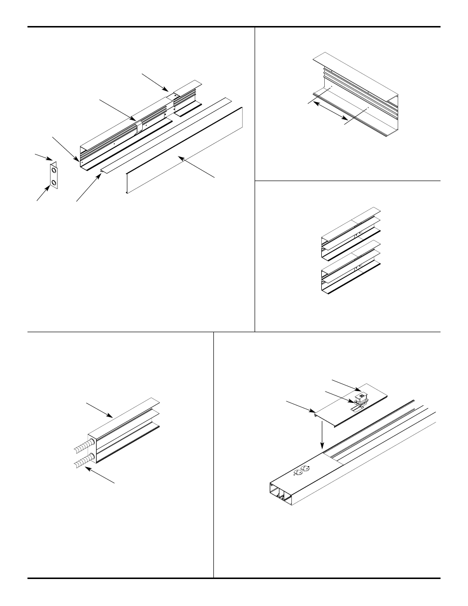
18"
[457mm]
AL5200 SYSTEM PRODUCT APPLICATION
AL5200B RACEWAY BASE
AL5200B RACEWAY BASE
To attach AL5200B Series Base sections to mounting
surface, drill 9/32" holes in The base (approx. 18" O.C.)
Fasten with #8 flat head screws.
Snap in AL5200D Divider into raceway base as shown.
Refer to cross-sectional drawings above for versatile
divider location.
1.Provide electrical feed through 1/2" or 3/4" [12.7mm or 19.1mm]
trade size KOs in AL5210B2 end caps.
2.Attach base section to mounting surface by drill 9/32" [7.1mm]
holes in the base and using #8 flat head screws.
3.Secure conductors in place with AL520wc Wire Clip.
4.Join additional raceway sections with two Al5201 Couplings.
5.Close ends with AL5210B2 Blank End Fittings.
6.Snap cover into base to complete installation.
IMPORTANT: All mounting methods must not exceed 4’-0"[1.22m]
interval and must result in a flush interior surface.
AL5210B2 (SHOWN)
AL5256 DEVICE PLACE SERIES
End feeding: AL5210B2/AL5210B3 and AL5210B3 Series
end fittings have concentric 1/2" and 3/4" trade size
KOs in end. Provide Electrical feed through KOs.
Insert fitting into End of raceway base. Secure in
place by tightening two screws.
To Install: Snap-in Bezel Cover into AL5256 Device place. After
installing the bezel, Snap-in the communication connectivity into
the bezel cover as required. Snap-in AL5656 Device Place Series
into AL5200B Raceway base to complete install.
Snap-in divider
(Optional)
1/2" OR 3/4"
TRADE SIZE CONDUIT
COMMUNICATION CONNECTIVITY INSERT
BEZEL COVER
AL5256 SERIES
AL5200 BASE
4
6
3
2
1
5