Legrand AL5200 Series Large Multi-Channel Aluminum Surface Raceway User Manual
Page 3
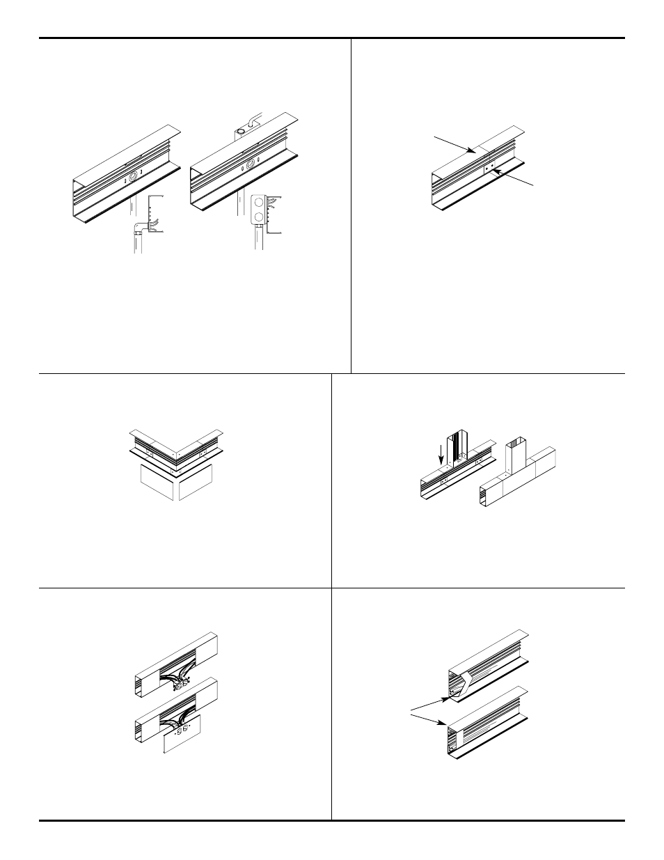
USING AL5214 WALL BOX CONNECTOR
AL5214 Wall Box Connector connects to two in line AL5200B
base sections via AL5201 Couplings supplied.
AL5201 COUPLING
At AL5200B Base section butt joints, slide two (2) AL5201
Coupling into first base section. Mount next base to
surface. Center couplings on joint. Tighten
Locking screws.
DIRECT FEED
AL5200WC
FEEDING FROM WALL BOX
AL5218 EXTERNAL CORNER COUPLING
AL5215 TEE ELBOW
At 90° Outside Corner, Position AL5218 External Elbow at end
of AL5200B Base. Slide other base section to other end of
AL52018Center couplings on joints and Tighten screws.
After wiring system. Snap on AL5218 mitered covers.
AL5215 Tee (shown above) and AL5216 Cross: Position fitting
at end of AL5200B Base. Install other base sections to other
ends of the fitting. Center couplings on joints and tighten
screws. Install fitting covers after wiring.
AL5246P SERIES DEVICES PLATE
AL5246P Series Device Plates, Install wiring to plate using #6
screws and "Keps"nuts provided. Snap device plate assembly
onto AL5200B base raceway.
AL5200WC WIRE CLIP
For retaining wires in long raceway run, Snap-in AL5200WC
Series Wire Clips into AL5200B Base as required.
BASE SECTION
AL5201