Installation instructions – Legrand DSBEA User Manual
Page 2
Legrand Delta Strut Solar Systems
have passed electrical/bonding
testing per UL 2703. The following
paragraph states the scope of the
UL standards:
These requirements cover rack
mounting systems and clamping devices
for flat-plate photovoltaic modules and
panels that comply with the standard
for Flat-Plate Photovoltaic Modules
and Panels, UL 1703, intended for
installation on or integral with buildings,
or to be freestanding (i.e., not attached
to buildings), in accordance with the
National Electrical Code, ANSI/NFPA 70
and Model Building Codes.
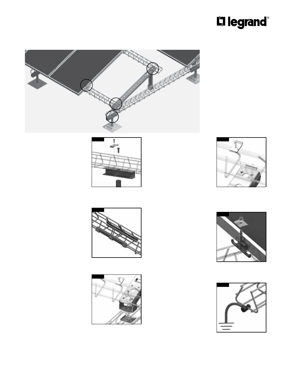
Installation Instructions:
1. Snap chalk lines for each DS
(Delta Strut) support row.
Rows should be located at
even intervals (not exceeding
maximum span of 60” or roof
loading requirements).
2. Snap a second set of chalk lines
at a right angle to position angle
support legs. Actual spacing
should be in accordance with
the drawings provided with each
DS shipment.
3. Install stanchions along support
row according to manufacturer’s
recommendations and roofing
requirements. Install at even
intervals with (not exceeding
maximum span of 60” or roof
loading requirements).
4. Attach DS to stanchions with
DSPEBK (Pedestal Extension
Bracket Kit). [Figure A]
5. Splice sections of DS together
using a DSSA splice (install
splices on both inside corners
of DS for a single splice). Torque
nuts to 6-8 ft/lbs. [Figure B]
6. Install and splice all DS rows
before beginning next steps.
7. Install DSBEA (Angle Support
Assemblies). Attach rear
support to DS support first by
pivoting leg forward then secure
to DS using clamp and self-
threading screw. Attach front
clamp in the same manner.
[Figure C]
8. Install DS stringers to angle
supports. Position DS in angle
bracket saddle, then secure
with a DSPCC (Connection
Clamp and self-threading
screw). [Figure D]
9. Splice sections of DS stringers
together using a DSSA splice
kit (install splices on both
inside corners of DS for a single
splice).
10. Position first PV panel at the
beginning of first run, check for
position and square, then attach
to DS using DSEHDC (End Bolt/
Clamp). Torque nuts to 6-8 ft/lbs.
11. Add next PV panel in run. Use
DSMHDC (Middle Bolt/Clamp -
Patent Pending) in areas where
two panels adjoin. Torque nuts
to 6-8 ft/lbs. [Figure E]
12. Pull feeder cabling into DS
stringer row. Connect PV cables
to feeder cables and secure
cabling to DS. Be aware that
cabling is live at this point.
13. Each solar row to be connected
to Earth as specified in NEC
using proper sized ground
conductor and UL Listed
Split-bolt lug connected to
Delta Strut. [Figure F]
Solar panels mounted to Delta Strut
on Membrane Roof with Stanchions
Bolt is tightened using socket
wrench or power drill thru
access hole.
DSPEBK
FIGURE A
Use punched pilot hole on
either side of bracket to allow
connection clamp clearance
from cross wire.
DSPCC
FIGURE D
Use two DSSA to splice any two
sections of Delta Strut tray.
DSSA
FIGURE B
DSMHDC is spring-loaded and
stays in position while panels
are positioned.
DSMHDC
FIGURE E
Use GNDSB split-bolt lug
grounding connector to
properly ground each solar
support row.
GNDSB
FIGURE F
Self-threading screw is
tightened using socket wrench
or power drill thru access hole.
DSBEA
DSBPW
DSPCC
FIGURE C
E
C
D
A