Installation instructions – Legrand DSBEA User Manual
Page 6
Legrand Delta Strut Solar Systems
have passed electrical/bonding
testing per UL 2703. The following
paragraph states the scope of the
UL standards:
These requirements cover rack
mounting systems and clamping devices
for flat-plate photovoltaic modules and
panels that comply with the standard
for Flat-Plate Photovoltaic Modules
and Panels, UL 1703, intended for
installation on or integral with buildings,
or to be freestanding (i.e., not attached
to buildings), in accordance with the
National Electrical Code, ANSI/NFPA 70
and Model Building Codes.
Installation Instructions:
1. Snap chalk lines for each
Universal Solar Support (USS)
row. Rows should be located at
even intervals with a maximum
distance of 60”. Actual spans
should be based upon roof
loading requirements.
2. Snap a second set of chalk
lines at a right angle to
correctly position the Delta
Strut stringers. Actual spacing
will vary based upon PV
panes size, angle and shading
requirements.
3. Place USS according to
chalk lines.
4. Load USS with concrete ballast
blocks in each of the three
cavities. Additional ballast can
be added to each USS base by
stacking ballast blocks on both
sides of the base. This should
be done within the loading
requirements of the roof and the
wind requirements of the array.
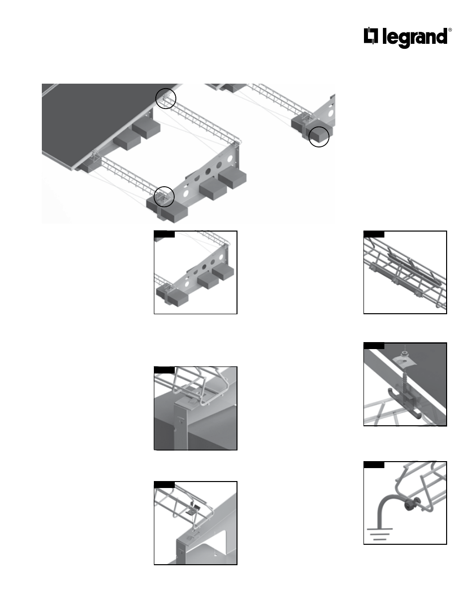
[Figure A]
5. Install Delta Strut stringers to
angle supports. Position Delta
Strut using the built-in position
tabs, then secure with a DSPCC
Connection Clamp and self-
threading screw. [Figures B, C]
6. Splice sections of Delta Strut
together using a DSSA splice
kit. Use both splices in the kit
for a single splice. Torque nuts
to 6-8 ft/lbs. [Figure D]
7. If you are using an Adjustable
Universal Solar Support (USSA),
you can adjust the support
height to make allowances for
low areas in the roof.
8. Attach cable bracing onto rear
and front of USS supports using
Cable Bracing Kit.
9. Place feeder cables into Delta
Strut stringer row(s).
10. Position first PV panel at the
beginning of first run, check for
position and square, then attach
to Delta Strut using DSEHDC
End Bolt/Clamp. Torque nuts to
6-8 ft/lbs.
11. Add next PV panel in run. Use
DSMHDC (Middle Bolt/Clamp -
Patent Pending) in areas where
two panels adjoin. Torque nuts
to 6-8 ft/lbs. [Figure E]
12. Connect PV cables and secure
cabling to Delta Strut. Be aware
that cabling is live at this point.
13. Each solar row to be connected
to Earth as specified in NEC
using proper sized ground
conductor and UL Listed Split-
bolt lug connected to Delta
Strut. [Figure F]
Roof mounted solar panels supported by
Delta Strut and USS Angle Support
DSMHDC is spring-loaded and
stays in position while panels
are positioned.
DSMHDC
Load Universal Solar Support
(USS) with standard 4” x
8” x 16” concrete blocks.
Ballast blocks can be
stacked for greater wind load
requirements.
Use punched pilot hole in USS
to allow connection clamp
clearance from cross wire.
DSPCC
Position Delta Strut stringers
using built in positioning tabs
on USS.
Use two DSSA to splice any two
sections of Delta Strut tray.
DSSA
Use GNDSB split-bolt lug
grounding connector to
properly ground each solar
support row.
GNDSB
FIGURE A
FIGURE B
FIGURE C
FIGURE D
FIGURE E
FIGURE F
B/C
E
A