Legrand WAPENCL Wireless Access Point Ceiling Enclosures User Manual
Page 3
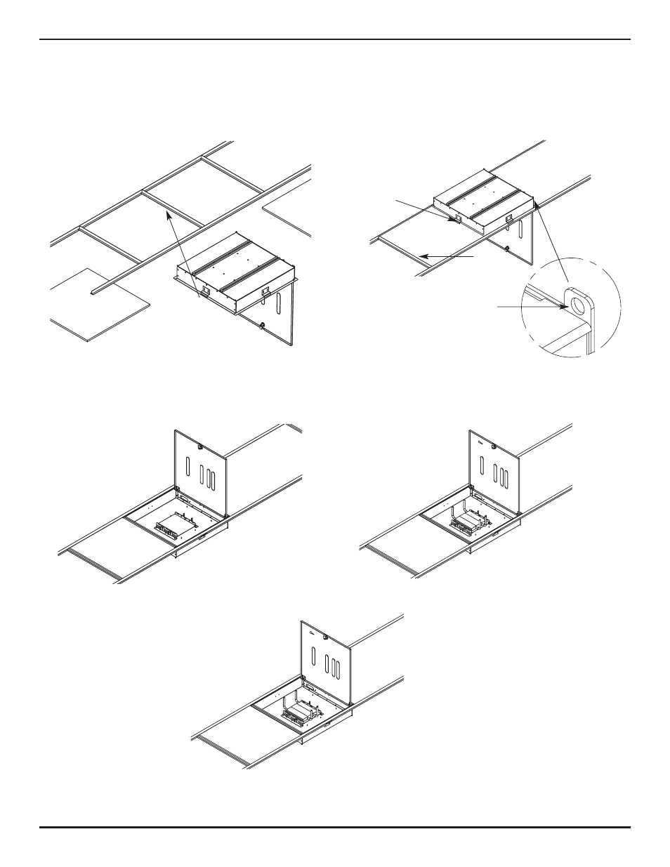
To Install WAPENCL-24-24-4 Wireless Access Point Ceiling Enclosure:
1.
2.
Remove 24" x 24" [609mm x 609mm] ceiling tile at
desired location, or remove 24" x 48" [609mm x 1219mm]
tile and cut to 24" x 24" [1219mm x 1219mm]. Insert
Enclosure into grid opening, place Enclosure Flanges
on T-Bar grid.
Adjust the four T-Bar Brackets to fit over the ceiling T-Bars,
tighten screws of each Bracket in place. Insert additional (if
required) T-Bar Support on cut tile side of Enclosure.
Secure Enclosure from four wire tie locations to building
ceiling structure (wire not included).
T-Bar
Brackets
T-Bar
Support
Wire Tie Off
(one located one
each corner of
the Enclosure)
View from above
View from above
3.
Remove fire stop material. Feed cables into Enclosure
through Fire Stop Bracket. Replace fire stop material once
Cables are fed (provide enough Cable for adjustments).
View from floor
4.
Install Wireless Access Point onto the adjustable base using
velcro straps provided. Connect all Cables to Wireless
Access Point and adjust unit to desired depth. Tighten wing
nuts to secure unit in place.
View from floor
5.
Remove required Antenna knockouts. Check
Antenna position with openings in door.
Reposition Wireless Access Point if needed
with openings. Install grommets into
openings. Re-install ceiling tiles. Remove
key, close door, and lock unit
(key is taped to inside of unit).
View from floor