Wiring directions, Caution, Sensor adjustment – Legrand CSU Series 32 kHz User Manual
Page 5
Advertising
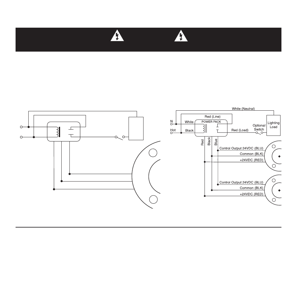
WIRING DIRECTIONS
Sensor wiring:
BLUE wire from power pack to BLUE wire from sensor.
RED wire from power pack to RED wire from sensor.
BLACK wire from power pack to BLACK wire from sensor.
Control Output 24VDC
Common
+24VDC
Lighting
Load
White (Neutral)
Red (Load)
Red (Line)
White
Black
Hot
N
POWER PACK
R
ed
Bl
ac
k
Bl
ue
Optional
Switch
(BLU)
(RED)
(BLK)
Call 800.223.4185 for Technical Support
CAUTION
TURN POWER OFF AT THE CIRCUIT BREAKER BEFORE WORKING WITH OR NEAR HIGH VOLTAGE.
Multiple Sensor Wiring
SENSOR ADJUSTMENT
THE SENSORS ARE FACTORY PRESET* TO ALLOW FOR QUICK INSTALLATION IN MOST
APPLICATIONS. However, verification of proper wiring, coverage, sensitivity, and time delay
adjustments can be made through the following steps.
Advertising