Warning, Installation & wiring – Legrand RW3U600 User Manual
Page 2
Time Delay
The time delay can be selected by the user during set up. It can be adjusted to
any of these fixed values:15 seconds/5 minutes/15 minutes/30 minutes. All of
the sensors related to the same load must be set for the same time delay. For
additional information on how to adjust it, please read the SENSOR ADJUSTMENT
& PROGRAMMING section of this installation manual.
Light Level
When the operating mode is set for occupancy sensor, Mode 2 (Auto-ON) this
feature prevents the sensor from automatically turning the lights ON if there is
already enough light in the area.
In a multi-way application, each sensor monitors the light level at it’s location.
If any sensor related to the load detects motion AND the measured light level in
that sensor’s area is lower than it’s Light Level setting, the load turns ON.
To adjust the light level, please read the SENSOR ADJUSTMENT &
PROGRAMMING section of this installation manual.
Coverage Area
The RW3U600 has a maximum coverage
range of 180 degrees and a coverage area
of 600 square feet (56 square meters). The
sensor must have a clear and unobstructed
view of the coverage area. Objects blocking
the sensor’s lens may prevent detection
thereby causing the light to turn OFF even
though someone is in the area.
Windows, glass doors, and other
transparent barriers will obstruct the
sensor’s view and prevent detection.
INSTALLATION & WIRING
WARNING
Disconnect power to the wall switch box by turning OFF
the circuit breaker or removing the fuse for the circuit before installing
the RW3U600, replacing lamps, or doing any electrical work.
1. Prepare the switch box.
After the power is turned OFF at the circuit breaker box, remove the existing
wall plate and mounting screws. Pull the old switch out from the wall box.
2. Identify the type of circuit.
You may connect the RW3U600 to a single pole or multi-way circuit. These
instructions describe only the 3-way circuit application. For information about
other applications, consult technical support. If you are unable to clearly
identify some or all of the wires mentioned in this manual, you should consult
with a qualified electrician.
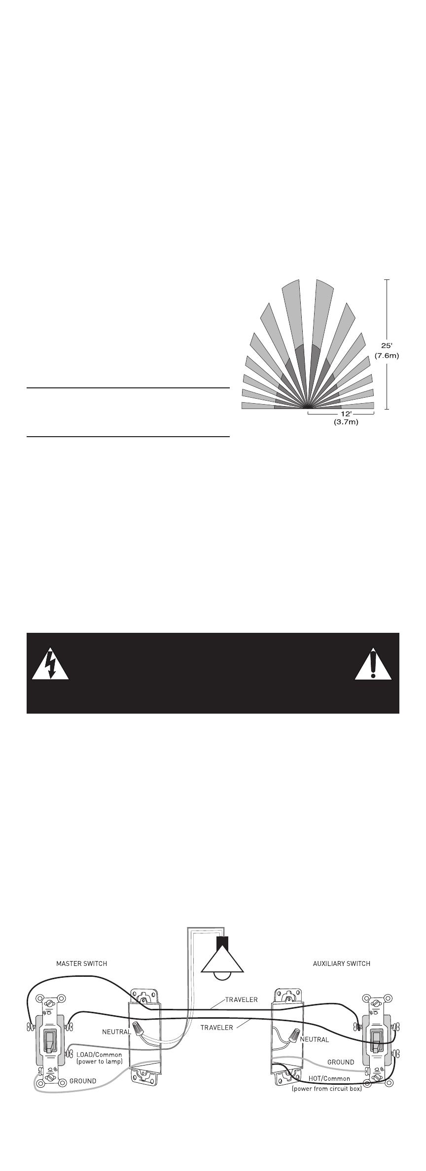
In a 3-way circuit (see Fig. 2), two traveler wires connect to both switches.
Another wire provides power from the circuit box to one of the switches. A wire
connects from one switch to the load. A ground wire may also be connected to
a ground terminal on the old switches. A neutral wire should also be present in
both wall boxes.
Fig. 2: Typical 3-Way Switch Wiring
www.passandseymour.com
Fig. 1: Sensor Coverage Area