Is-0385 rev. b – Legrand IC5001 User Manual
Page 2
INSTRUCTION / INSTALLATION SHEET
Selective Call Intercom Distribution
Module
IS-0385 Rev. B
301Fulling Mill Road, Suite G
Middletown, PA 17057
Phone (800) 321-2343 / Fax (717) 702-2546
www.onqlegrand.com
©Copyright 2011 by Legrand All Rights Reserved.
Page 2 of 4
NOTE: It is important to keep all Category 5e cable runs, regardless of use, at least 12 inches away
from AC electrical cables. If it proves necessary to cross an existing AC cable, do so only at a 90
degree angle.
B. “Trim-out”
steps:
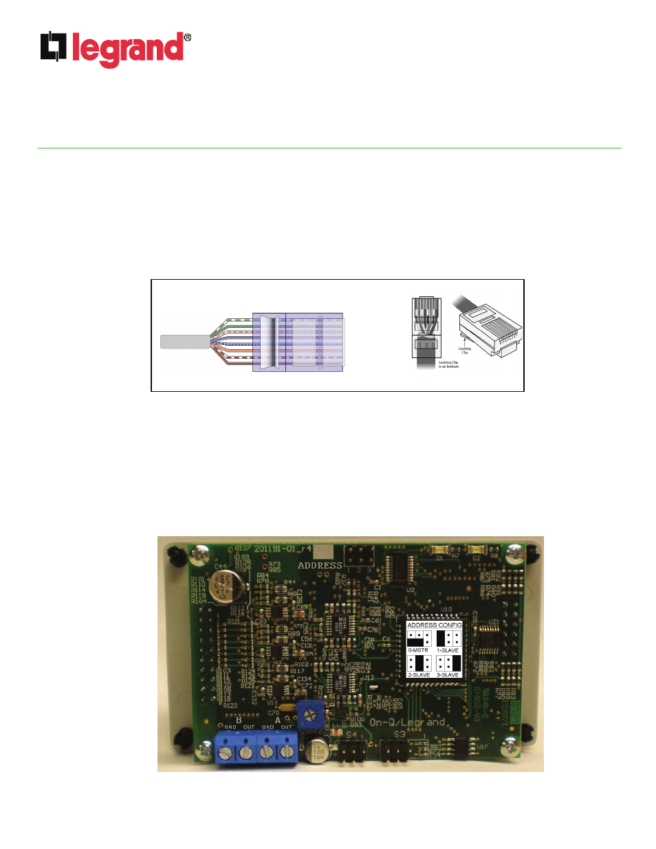
NOTE: All components in the Selective Call Intercom System use RJ45 plugs terminated to the T568A
wiring standard. Refer to Figure 2 for correct T568A termination for RJ45 plugs.
RJ-45
Pin
1 – White/Green
2 – Green
3 – White Orange
4 – Blue
5 – White/Blue
6 – Orange
7 – White/Brown
8 – Brown
RJ-45
Pin
1 – White/Green
2 – Green
3 – White Orange
4 – Blue
5 – White/Blue
6 – Orange
7 – White/Brown
8 – Brown
Figure 2
1. As shown in Figure 3, there is an “ADDRESS” jumper block located at the top of the rear of the Selective
Call Intercom Module. This jumper block is used to select the Master module, and up to three Slave
modules when cascading Modules. Each Selective Call Module is shipped with the jumper in the Master
position. Use the diagram to correctly position the jumper for multi-module systems.
2. As also shown in Figure 3, there is also a four position terminal block located on the lower left corner
of the rear of the Selective Call Intercom Module. These are Open Collector Outputs labeled “A” and
“B” (ground and output connectors for each). At any Room Unit, you can configure the “A” Door Strike
(“Release”) and/or “B” Alert (“Trigger”) outputs to be enabled or disabled. See Figure 4 and Figure 5
for an examples of the wiring associated with this terminal block.
Figure 3
Figure 2