Instruction / installation sheet telecom modules, Is-0058 rev. e, Figure 3 – Legrand 1267062-01 User Manual
Page 2
INSTRUCTION / INSTALLATION SHEET
Telecom Modules
IS-0058 Rev. E
301 Fulling Mill Road, Suite G
Middletown, PA 17057
Phone (800) 321-2343 / Fax (717) 702-2546
www.onqlegrand.com
©Copyright 2007 by On-Q/Legrand All Rights Reserved.
Page 2 of 3
NOTE: White wires may not have color trace
stripe. Keep white wire paired with
appropriate colored wire based on twist.
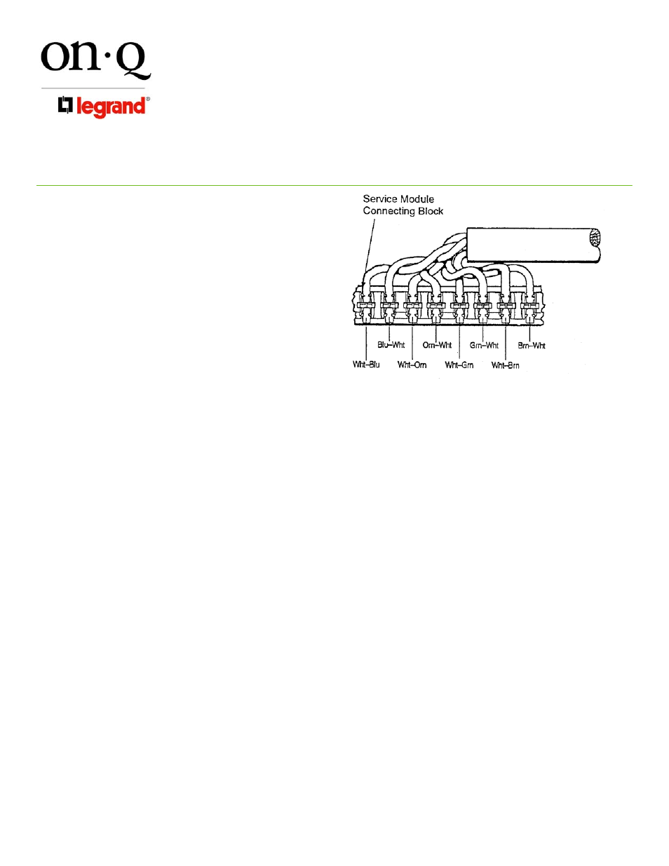
4) Without untwisting cable, position the wires
in individual slots (see Figure 3).
5) Punch-down and trim wires using On-Q
Punch-Down Tool (P/N 363293-01 or
equivalent).
6) Remove excess wire & tug slightly to
ensure wire is securely installed in
connector.
C. Incoming Service Cable Installation
(Telecom Expansion)
1) Connect one end of the supplied CAT5E
jumper cable to the RJ45 jack labeled
“Test/Bridge” on the 1x6 Telecom Module
and connect the other end to the RJ45 jack
labeled “Bridge In” on the Telecom Expansion Module.
2) To install additional Telecom Expansion Modules, connect one end of the supplied CAT5E jumper to the
RJ45 jack labeled “Bridge Out” on the first Telecom Expansion Module and connect the other end to the
“Bridge In” RJ45 on the second Telecom Expansion Module.
3) If connecting to a 1x11 Basic Telecom Module (P/N 363484-01), connect the CAT5E jumper between the
RJ45’s labeled “Test Bridge” and “Bridge In”.
D. Outlet Cable Termination
1) Identify outlet cable and route to a numbered 110 punch-down block. In routing cable, allow slack for
bundling to the side and avoiding other cable terminations. Trim cable about 2 inches beyond connector.
2) Strip off approximately 4 inches of the outer jacket using On-Q Strip Tool (P/N 363292-01 or equivalent).
3) Position pairs over color-coded slots on the connector (see Figure 3).
4) Without untwisting cable, position the wires in individual slots (see Figure 3).
5) Punch-down and trim wires using On-Q Punch-Down Tool (P/N 363293-01 or equivalent).
6) Remove excess wire and tug slightly on cable to ensure wire is securely installed in connector.
7) Record room name/number to connector number on a wire layout list and place list in enclosure.
8) Repeat until all outlets are connected.
NOTE: To complete proper cross connect, install a CAT5E jumper (P/N 363201-27).
E. Securing
Cables
After all cables are connected to the module, the cables should be bundled and grouped to allow ease of
maintenance. On-Q Wire Management Straps (P/N 363491-01), may be used to bundle cable.
4. Testing
A. To test the outlet wiring from the Telecom Modules to the wall outlets, turn all switches on “Test Switch” to
“OFF”. Insert line tester into the RJ45 jack labeled “Test/Bridge”. Perform check at each wall outlet. All
outlets, including those on the Telecom Expansion Module, will be testable.
Figure 3