Lencore Spectra i.Net: G41 User Manual
Page 2
Model
G41
SPECTRA – i.Net
®
v2.0
Lencore Acoustics Corp. One Crossways Park Drive West Woodbury, NY 11797 p 516-682-9292 f 516-682-4785 [email protected]
Spectra i.Net®, Spectra®, CrossNetOne™, CrosswaysOne™ are trademarks of Lencore Acoustics Corp. All rights reserved. © Copyright 2013
The IR Touch Pad Controller comes with all dip switches in the down
position by default.
This default setting will allow the IR Touch pad controller to be used
with the IR Hub model G482 out of the box. If you do not have the
IR Hub model G482 you can connect the IR touch pad directly to an
OP. This will require configuration.
PROGRAMMING THE IR TOUCH PAD
CONTROLLER:
The configuration of the IR touch pad controller is done thru dip
switches located on the back side of the board. (See diagram
above)
The list below shows all possible configurations for the IR touch
pad. Configurations will allow you to: control individual channels
such as channel A, B, C, D (individually) or All channels, also config-
ure whether or not the switch (buttons) on the front panel of the IR
touch pad are active or not and if the IR sensor is active or not.
To configure dip switches: locate the back of the IR touch pad and
turn board to the right 90o. The RJ45 connector receptacle will now
be oriented towards the right. The small pins numbered 1-8 will
now be in the middle left of the board. Thee small pins can be set
to either “UP” or “DOWN” which can be done with a small screw-
driver.
Use the list below to find what dip switches need to be changes for
your particular install.
OTHER SYSTEMS ALSO AVAILABLE
Spectra®, Spectra Tangent™, Spectra Emerald™
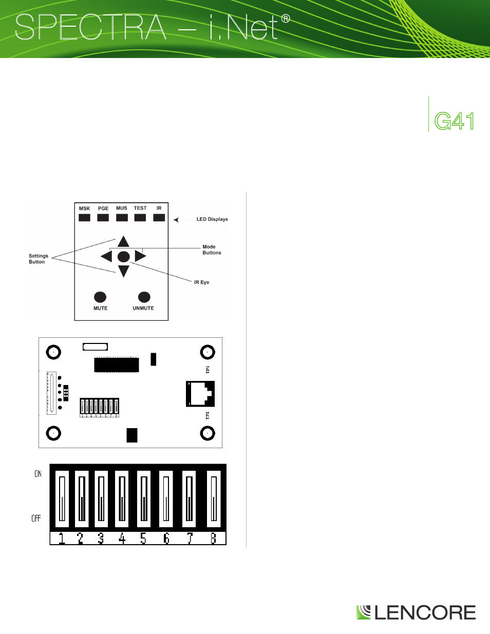
Back of Wall Plate (board turned right 90°)
Exploded View: Dip Switches (on board turned right 90°)
IR TOUCH PAD CONTROLLER CONFIGURATION MANUAL
Front of Wall Plate