Installation and operating instructions, Connection diagram, Interconnection diagram – Louroe Electronics LE-572 User Manual
Page 3
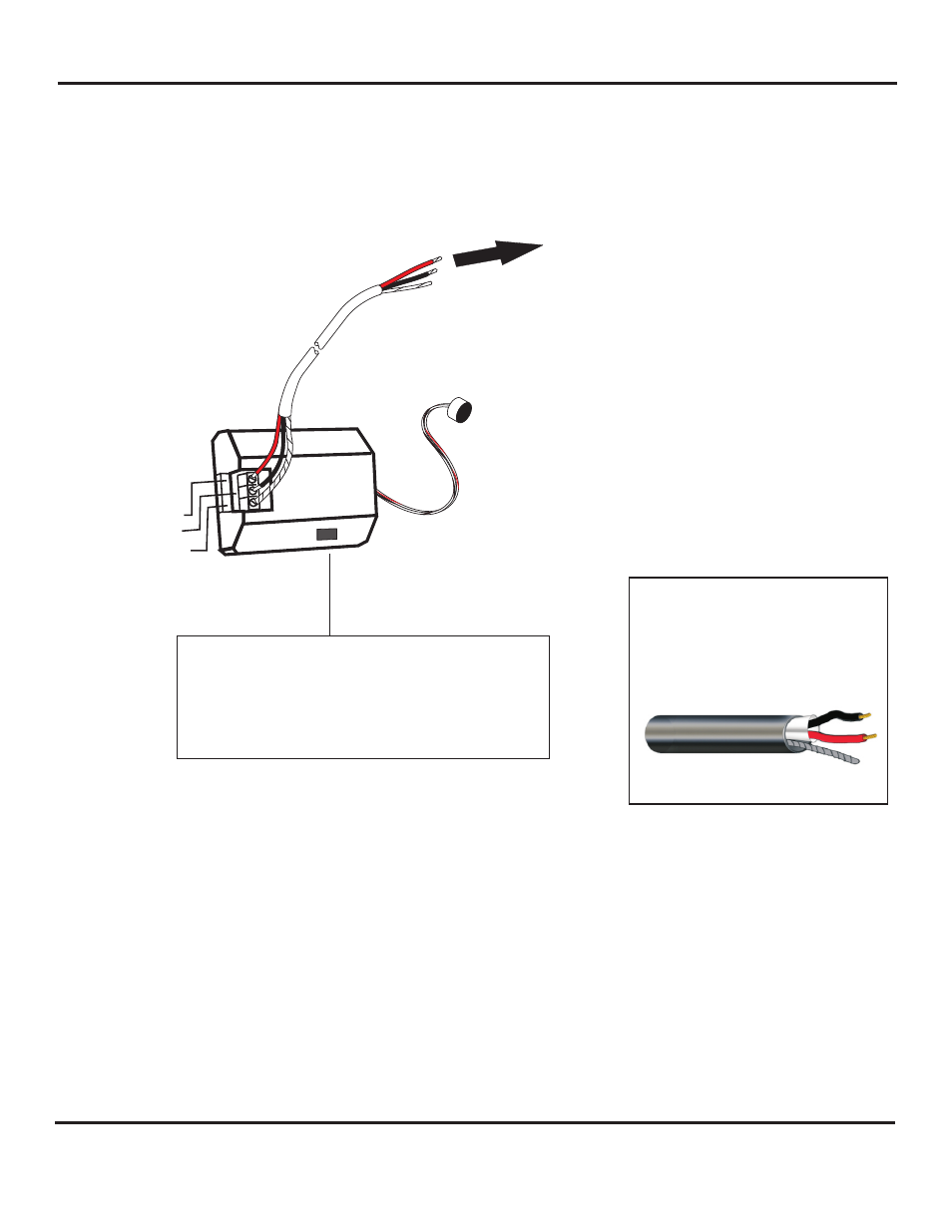
CONNECTION DIAGRAM
TO LOUROE BASE
STATION OR AUDIO
AUDIO INTERFACE
ADAPTER
RED
wire (12 Vdc) connects to Terminal A
BLACK wire (Audio) connects to Terminal B
wire
(Ground) connects to Terminal C
BARE
If using recommended wiring (West Penn 452)
INSTALLATION TIPS
1. Use overall shielded audio cable only. West Penn 452, Belden 8451 or equivalent.
UNSHIELDED CABLE IS NOT SATISFACTORY FOR SOUND SYSTEMS.
2. When used at a cash register checkout, microphone should be installed closer to the customer rather than the cash
register, as the drawer sound could dominate the recording. It should be installed closest to the
area to be monitored and documented.
3. Avoid installing microphone near air vents, air conditioners, fans and other equipment that generate
high sound and air pressure.
4. If microphone is installed in a police interview room, room should be conditioned with any type of carpeting, acoustical
ceiling tiles, acoustical foam, etc. to reduce echo. This will enhance the quality of live and recorded audio.
5. The APR-1 and microphone should have a barrier or solid wall between them in order to avoid audio
feedback, especially when they are in close proximity to each other. If no barrier, microphone should be at least 25’
from APR-1 to avoid acoustical feedback.
2 Conductor shielded cable, 22
gauge with a 24 gauge drain wire
NOTE:
Unshielded cable is not
satisfactory for audio systems
WIRING REQUIREMENTS
West Penn 452 or equivalent
A (12 Vdc)
B (Audio)
C (Ground)
A
L
C
B
N
Page 3 of 4
LOUROE ELECTRONICS 6 9 5 5 VA L J E A N AVENUE, VAN NUYS, CA 91406
TEL (818) 994-6498
FAX
994-6458
website: www.louroe.com e-mail: [email protected]
(818)
®
INSTALLATION AND OPERATING INSTRUCTIONS
INTERCONNECTION DIAGRAM
MICROPHONE GAIN ADJUSTMENT
The microphone has an audio output gain potentiometer.
Microphone is always shipped with a 0dB output. If it’s necessary
to change the gain of the microphone, insert a small screwdriver
into the potentiometer rotate clockwise to increase or
counterclockwise to decrease. Maximum gain is +10dB
Cgc_mic_inst_12/14