Interconnection diagram, Installation and operating instructions, Fig. 4 – Louroe Electronics ASK-4 601 User Manual
Page 4
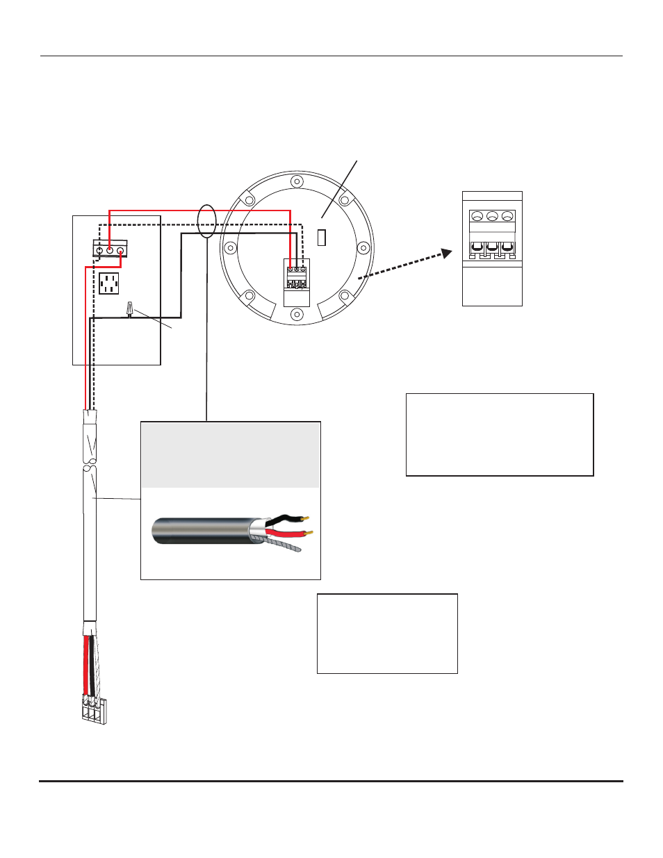
A B C
A B C
V E R I FA C T A
M I C R O P H O N E
L
N
MS-1
Mute Switch
A B C
TERMINAL
BLOCK OF
VERIFACT A
MICROPHONE
Gain adjust switch
(factory set)
Terminal Block of
Louroe APR-1 Base Station
or
Audio Interface Adapter
All Louroe microphones
are compatible with the MS-1
Model Verifact A is shown
as an example
2 Conductor shielded cable, 22
gauge with a 24 gauge drain wire
NOTE:
Unshielded cable is not
satisfactory for audio systems
WIRING REQUIREMENTS
West Penn 452 or equivalent
A
B
C
WIRE NUT
Refer to Louroe Base Station
or
Audio Interface Adapter
Installation and operating
instructions
www.louroe.com
INTERCONNECTION DIAGRAM
VERIFACT A MICROPHONE TO MS-1 AND APR-1 BASE STATION
INSTALLATION AND OPERATING INSTRUCTIONS
Page 4 of 8
LOUROE ELECTRONICS 6 9 5 5 VA L J E A N AVENUE, VAN NUYS, CA 91406
TEL (818) 994-6498
FAX
994-6458
website: www.louroe.com e-mail: [email protected]
(818)
®
Fig. 4
ASK4_601_inst 2/15
®
®