Installation and operating instructions – Louroe Electronics TLM-W User Manual
Page 2
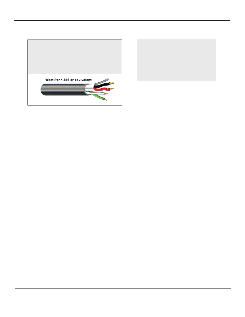
WIRING REQUIREMENTS
4 Conductor consisting of:
+
2 Conductor shielded, 20 gauge with 22
gauge drain (microphone connection)
+
2 Conductor unshielded, 18 gauge (speaker
connection)
All in the same jacket
TLM MICROPHONE AND SPEAKER CONNECTIONS
Using 4- Conductor cable shown below as example, connect as follows: (See connection diagram p. 3)
If using wiring from other manufacturers, color
code may vary.
MICROPHONE CONNECTION OF TLM-W
On the back side of TLM-W face plate is a PC Board with a small 3-pin terminal block marked A,B,C.
1) Connect RED wire to terminal block marked “A” (+12Vdc)
2) Connect BLACK wire to terminal block marked “B” (Audio Output)
3) Connect DRAIN wire (bare) to terminal blocked marked “C “ (Ground)
SPEAKER CONNECTION
Attached to the 70V transformer of TLM-W are two speaker wires, GREEN and WHITE.
Using wire nuts,
1) Connect GREEN wire (positive) of recommended cable to GREEN wire of transformer
2) Connect WHITE wire (negative) of recommended cable to WHITE wire of transformer
OF TLM-W
TLM-W CONNECTION TO LOUROE BASE STATION
Connect the other end of cable to the terminal block(s) on the rear panel of the base station.
Most Louroe base stations have terminal blocks identical or similar to the TLM-W.
Should blocks differ from the example below, refer to the installation instructions for the specific base station being
used.
For microphone connection:
1) Connect terminal A of TLM-W to terminal A of Louroe Base Station
2) Connect terminal B of TLM-W to terminal B of Louroe Base Station
3) Connect terminal C of TLM-W to terminal C of Louroe Base Station
For speaker connection:
4) Connect GREEN wire of TLM-W to terminal SP of Louroe base station (positive)
5) Connect WHITE wire of TLM-W to terminal G of Louroe base station (negative)
Wire Color Code
RED - 12Vdc Power
BLACK - Audio Output
BARE - Ground
GREEN - Speaker Positive
WHITE - Speaker Negative
}
}
Microphone
Portion
Speaker
Portion
INSTALLATION AND OPERATING INSTRUCTIONS
Page 2 of 8
LOUROE ELECTRONICS 6 9 5 5 VA L J E A N AVENUE, VAN NUYS, CA 91406
TEL (818) 994-6498
FAX
994-6458
website: www.louroe.com e-mail: [email protected]
(818)
®
tlm_w_inst_3/15