Installation and operating instructions, Connections to plug-in connector (audio), Relay connections – Louroe Electronics DG-12II User Manual
Page 15: Connector to header connections
PAGE 12 of 28
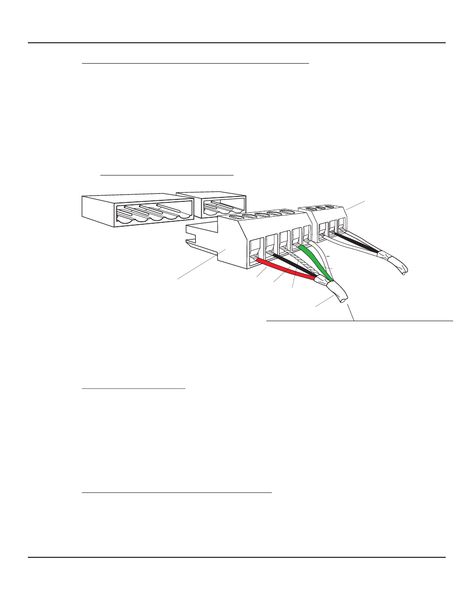
CONNECTIONS TO PLUG-IN CONNECTOR (AUDIO):
Prior to connecting the microphone cables to the DG-12 plug-in connectors, each
microphones should be checked for proper operation. This can be done quickly by
connecting the Louroe PTA (portable test amplifier) to each microphone cable. The battery
powered PTA powers the microphone under test and monitors its output though the installed
cabling. This eliminates any faulty microphone circuits before final testing. After each
microphone is tested, connect cables coming from remote station or MLA-6 Mixer to the
5-pin plug-in connector (supplied) as shown in Fig. 7. Observe wire color coding. When no
speaker is used in the remote station, there are no connections made on terminals marked
“SP” and “G”.
II
RELAY CONNECTIONS:
One single pole, double throw relay contact is available from each zone alert circuit, for
connections to outside equipment. Each relay contains three terminal outputs: COM
(common), NC (normally closed) and NO (normally open). Connection to the outside
equipment can be done by connecting the cable to the 3-pin plug-in connector (supplied)
as shown in Fig. 7. To prevent losing the connectors until needed, plug the connectors to
the headers in the rear panel of the DG-12II when relay outputs are not in use. Maximum
rating of the relay contact is 0.5A @ 125 Vac or 1.8A @ 30 Vdc. DO NOT EXCEED
CURRENT RATING OR RELAY MAY BE DAMAGED.
CONNECTOR TO HEADER CONNECTIONS:
With power OFF, plug in the 5-pin plug-in connector to its respective header at the rear of
the DG-12II. See Fig. 7. Plug-in connector for zone 1 to header of zone 1; connector for
zone 2 to header of zone 2, etc... Plug in the 3- pin plug in connector to its respective relay
header. Push the connector firmly against the header until the lock snaps in.
Fig. 7 Connections to the DG-12 using 5-pin connector
II
A
B
C
SP
G
COM
NC
NO
5-PIN CLOSED HEADER
3-PIN CLOSED HEADER
5-PIN PLUG IN CONNECTOR (SUPPLIED)
AUDIO
3-PIN PLUG IN CONNECTOR
RELAY
REAR OF DG-12
II
WEST PENN 356
BLACK
RED
BARE
GREEN
WHITE
FROM MLA-6 OR TLI (SPEAKER/MICROPHONE UNIT)
DG_12II_6/11
LOUROE ELECTRONICS 6 9 5 5 VA L J E A N AVENUE, VAN NUYS, CA 91406
TEL (818) 994-6498
FAX
994-6458
website: www.louroe.com e-mail: [email protected]
(818)
®
INSTALLATION AND OPERATING INSTRUCTIONS