Sa-1a, Installation and operating instructions, Seldom used) – Louroe Electronics SA-1A User Manual
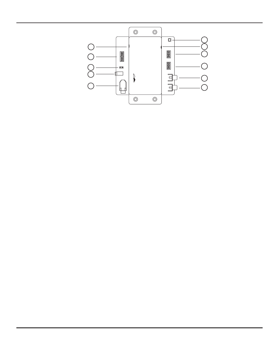
Page 2: Fig. 1 sa-1a panel description
[1]
Sensitivity Setting Potentiometer
Sets the level of sound for activating the switch. Rotating the
potentiometer clockwise increases the sensitivity of the VOX switch. The
more sensitive the setting, the less sound level is needed to trigger the
unit.
[2]
MIC-IN Terminal Block
Connects to remote microphone or other audio devices. May be
connected to balanced or unbalanced audio source. Mic input is factory
set for unbalanced connections. When using balanced audio source,
remove jumper marked “JP4”. Louroe microphones are unbalanced
and utilize terminals A, B1 and C.
[3]
Jumper
JP4 jumper is removed when using a balanced audio source.
(microphone with a 600
W
balanced output)
[4]
Power Jack
+ 12Vdc AC Adapter (supplied).
[5]
MIC IN/OUT Jack
Unswitched audio output from remote microphone or other audio device
can be monitored using audio jack. May also be used to accept audio
from external sources without using the Mic Input Terminal Block[2].
[6]
Triggered MIC Out Jack
Switched audio output from remote microphone or other audio device
can be monitored using RCA jack. No audio is produced until the unit is
triggered.
[7]
Line OUT Jack
Unswitched audio output level from RCA jack can be adjusted by
rotating the Sensitivity Setting Potentiometer[1]. Rotating clockwise
increases the threshold sensitivity as well as the audio output. Rotating
counterclockwise decreases audio output.
[8]
Relay Output 1
3-Pin terminal block marked NO(normally open), COM (common), NC
(normally closed). Provides relay closure when the unit is triggered.
Maximum contact rating is 5A @ 30 Vdc or 5A @ 277 Vac.
[9]
Relay Output 2
3-Pin terminal block marked NO(normally open), COM (common), NC
(normally closed). Provides a second relay closure when unit is
triggered.
[10]
Latch Release Potentiometer
Sets relay latching time. Rotate the potentiometer shaft slowly clockwise
for more time release or counterclockwise for less. Time can be set from
0.5 to 60 seconds.
[11]
Alarm LED
Illuminates when unit is triggered or is in alarm. Turns OFF when the
latching time for the relay expires.
(seldom used)
SA-1A
SOUND ACTIVATED SWITCH
MIC IN
A
SENSITIVITY
SETTING
LATCH RELEASE
TIME
12 Vdc
JP4
B1
B2
C
REL
A
Y 1
LINE OUT
TRIGGERED
MIC OUT
NC
COM
NO
REL
A
Y 2
NC
COM
NO
E
L
OUROE
LECTRONIC S
11
10
9
8
7
6
5
4
3
2
1
Fig. 1 SA-1A Panel Description
Page 2 of 8
LOUROE ELECTRONICS 6 9 5 5 VA L J E A N AVENUE, VAN NUYS, CA 91406
TEL (818) 994-6498
FAX
994-6458
website: www.louroe.com e-mail: [email protected]
(818)
®
INSTALLATION AND OPERATING INSTRUCTIONS
sa1a-inst_3/15