Wallmount – LSC Lighting Redplate Installation Guide User Manual
Page 2
Advertising
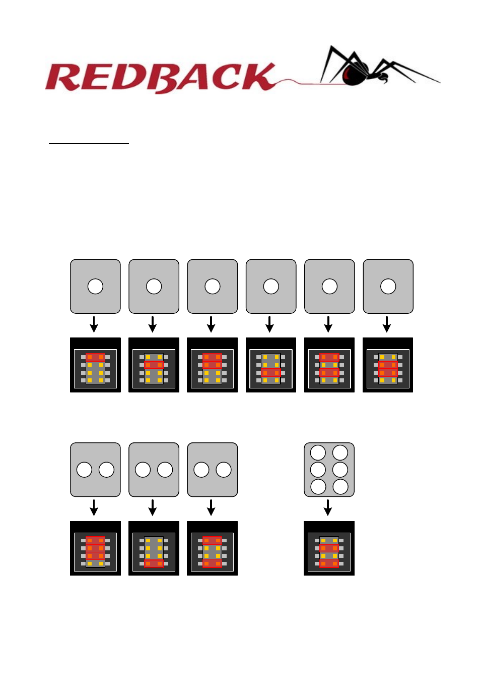
MODE SETTING:
Mode setting connects the Redback Wall plate buttons to the Redback Wallmount dimmer
memories. The diagrams below depict the Redback Wall plate options with the control memory
number shown inside the circle. From the diagrams below, locate the drawing which shows
the required memory / button configuration and set the Mode jumpers accordingly.
Note the settings below are the only valid configurations.
A mode must be set for the plate to operate correctly.
Redback Wallmount Plate User manual RDPL-T01U-A0. July 2011 © LSC lighting Systems
MODE
MODE
MODE
MODE
MODE
MODE
1
2
6
5
4
3
MODE
MODE
MODE
MODE
2
3
1
2
3
4
5
6
MODE
MODE
3
4
1
2
5
6
ONE BUTTON PLATES
TWO BUTTON PLATES
SIX BUTTON PLATE
For more information please visit www.lsclighting.com.au
Wallmount
2
Advertising