Connection of speaker systems, Basic connections, Connection of ac power cable – Marantz PM5003 User Manual
Page 11: Wiring speaker cable, English
8
BASIC
OPERA
TION
ADV
ANCED
CONNECTION
REMOTE CONTROLLER
OPERA
TION
TROUBLESHOOTING
OTHERS
NAMES AND
FUNCTIONS
BASIC
CONNECTIONS
ENGLISH
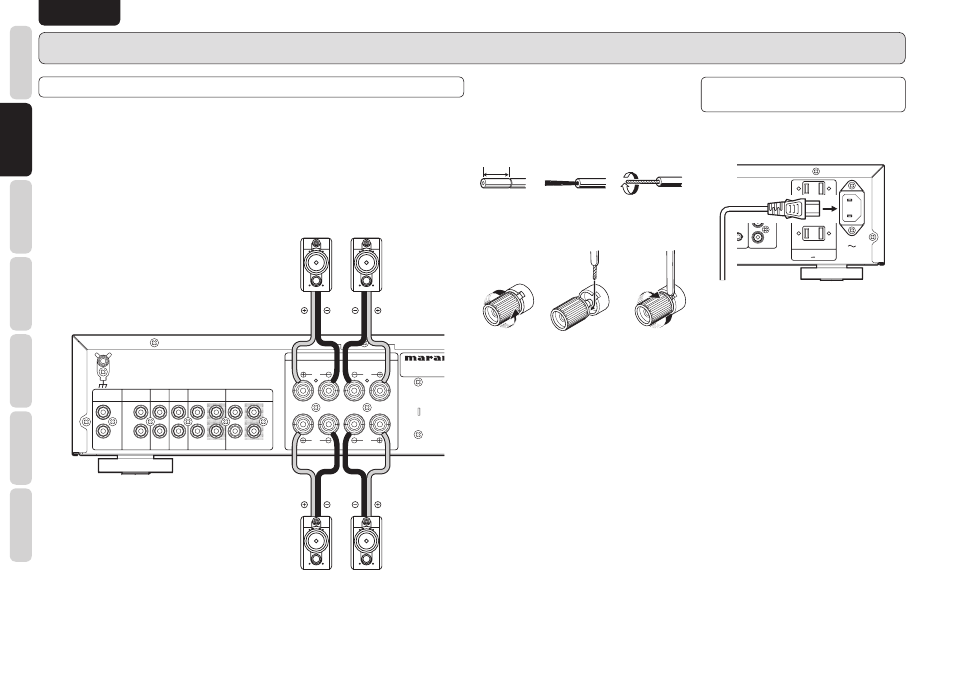
CONNECTION OF SPEAKER SYSTEMS
This unit is equipped with two sets of SPEAKER SYSTEM terminals––SYSTEM A terminals and SYSTEM
B terminals. Usually connect your speaker system to the SYSTEM A terminals.
• The speakers in the speaker system should have an impedance between 8 and 16 ohms. If speakers with
an impedance of less than 8 ohms are connected, the protection circuitry may be activated during play.
• Connect the Right channel speaker to the R terminals, and the Left channel speaker to the L terminals.
• The output terminals have positive (+: Red) and negative
(–: Black) polarity, and each speaker also has the same polarity (+ and –). When connecting the speaker,
be sure to connect the terminals with the same polarity (+ with +, – with –).
R
OUT
OUT
IN
IN
OUT
OUT
IN
IN
L
R
L
R
L
R
L
R
L
PHONO
PHONO
TUNER
TUNER
CD
CD
AUX
AUX / DVD
DVD
RECORDER 2
RECORDER 2
(MD
MD
/
TAPE
TAPE)
RECORDER 1
RECORDER 1
(CD-R
CD-R)
SPEAKER SYSTEMS
SPEAKER SYSTEMS
SYSTEM B
SYSTEM B
CLASS 2 WIRING
CLASS 2 WIRING
SYSTEM A
SYSTEM A
PHONO
PHONO
GND
GND
BASIC CONNECTIONS
7
Wiring speaker cable
• Be careful not to short circuit in wiring speaker
cables.
• Peel off the corting of speaker cable as shown
below.
Approx. 1 cm
Cut the corting of
cable.
Peel off the edge
of cable.
Twist conductors.
• Wiring with speaker cable.
Turn counter-
clockwise to
loosen.
Insert conductor
of cable.
Turn clockwise to
tighten.
Your speaker system must satisfy the below
conditions. If it does not, the PM5003’s protective
circuit will active, whereby preventing proper
playback. In some cases, the amplifier and speakers
may be damaged.
• If using 1 set of speakers, total speaker
impedance must be 4 ohms or more.
• If using 2 sets of speakers, total speaker
impedance must be 8 ohms or more.
CONNECTION OF AC
POWER CABLE
1.
Plug the power cable into AC IN jack on the
back panel.
REMOTE
REMOTE
CONTROL
CONTROL
ASHER
FLASHER
IN
IN
AC OUTLETS
AC OUTLETS
120V 60Hz
120V 60Hz
UNSWITCHED
UNSWITCHED
120W 1A MAX
120W 1A MAX
SWITCHED
SWITCHED
120W 1A MAX
120W 1A MAX
IN
IN
OUT
OUT
AC IN
AC IN
2.
Turn on the power switch of the audio unit
(amplifier, etc.) that is connected with this unit.
Set the selector on the connected unit to this
unit.
3.
Plug the power cable into an AC outlet.