Maytag MVWB750WB Dimension Guide User Manual
Top-loading washer, Drain system, Product model numbers overall dimensions
Top-Loading Washer
PRODUCT MODEL NUMBERS
OVERALL DIMENSIONS
MVWB400V, MVWB700V,
MVWB750W, MVWB300W,
MVWB450W, MVWB750W,
MVWB850W, MVWB755Y
Electrical: A 120 volt, 60 Hz., AC only, 15- or 20-amp,
fused electrical supply is required. A time-delay fuse
or circuit breaker is recommended. It is recommended
that a separate circuit serving only this washer be
provided.
Because Whirlpool Corporation policy includes a continuous commitment to improve
Dimensions are for planning purposes only. For complete details, see Installation
our products, we reserve the right to change materials and specifications without notice.
Instructions packed with product. Specifications subject to change without notice.
Ref. W10240438B
01/2011
DRAIN SYSTEM
Drain system can be installed using a floor drain,
wall standpipe, floor standpipe, or laundry tub.
Select method you need.
The standpipe drain requires a minimum diameter
standpipe of 2" (51 mm). The minimum carry-
away capacity can be no less than 17 gal. (64 L)
per minute. A 2" (51 mm) diameter to 1" (25 mm)
diameter standpipe adapter kit is available. See
“Tools and Parts”.
The top of the standpipe must be at least 39" (990
mm) high and no higher than 96" (2.4 m) from the
bottom of the washer.
The laundry tub drain system needs a minimum 20 gal. (76 L)
capacity laundry tub. The top of the laundry tub must be at least
39" (990 mm) above the floor and no higher than 96" (2.4 m) from
the bottom of the washer.
The floor drain system requires a siphon break that may
be purchased separately. See “Tools and Parts”. The siphon
break must be a minimum of 28" (710 mm) from the bottom
of the washer. Additional hoses might be needed.
Wall standpipe Floor standpipe
Laundry Tub
Floor
39"
(990 mm)
39"
(990 mm)
28"
(710 mm)
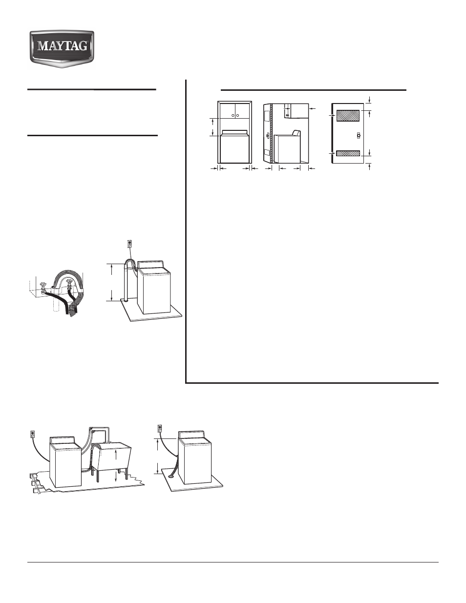
Spacing for recessed area or closet installation
All dimensions show recommended spacing allowed, with tested spacing of
0" (0 mm) clearance on sides.
Additional spacing should be considered for ease of installation and
■
servicing.
Additional clearances might be required for wall, door, and floor
■
moldings.
Additional spacing should be considered on all sides of the washer to
■
reduce noise transfer.
For closet installation, with a door, minimum ventilation openings in the
■
top and bottom of the door are required. Louvered doors with equivalent
ventilitation openings are acceptable.
Companion appliance spacing should also be considered.
■
Front view
Side view
* Required spacing
17"*
(432 mm)
27
1
/
2
"
(699 mm)
1"
(25 mm)
27"
(686 mm)
5"*
(127 mm)
14"* max.
(356 mm)
48 in.
2
*
(310 cm
2
)
24 in.
2
*
(155 cm
2
)
1"
(25 mm)