Step 9, Step 10a, Step 11 – Maytag LAT9420AAE Installation User Manual
Page 5: Step 12, Step 10b
CLIP
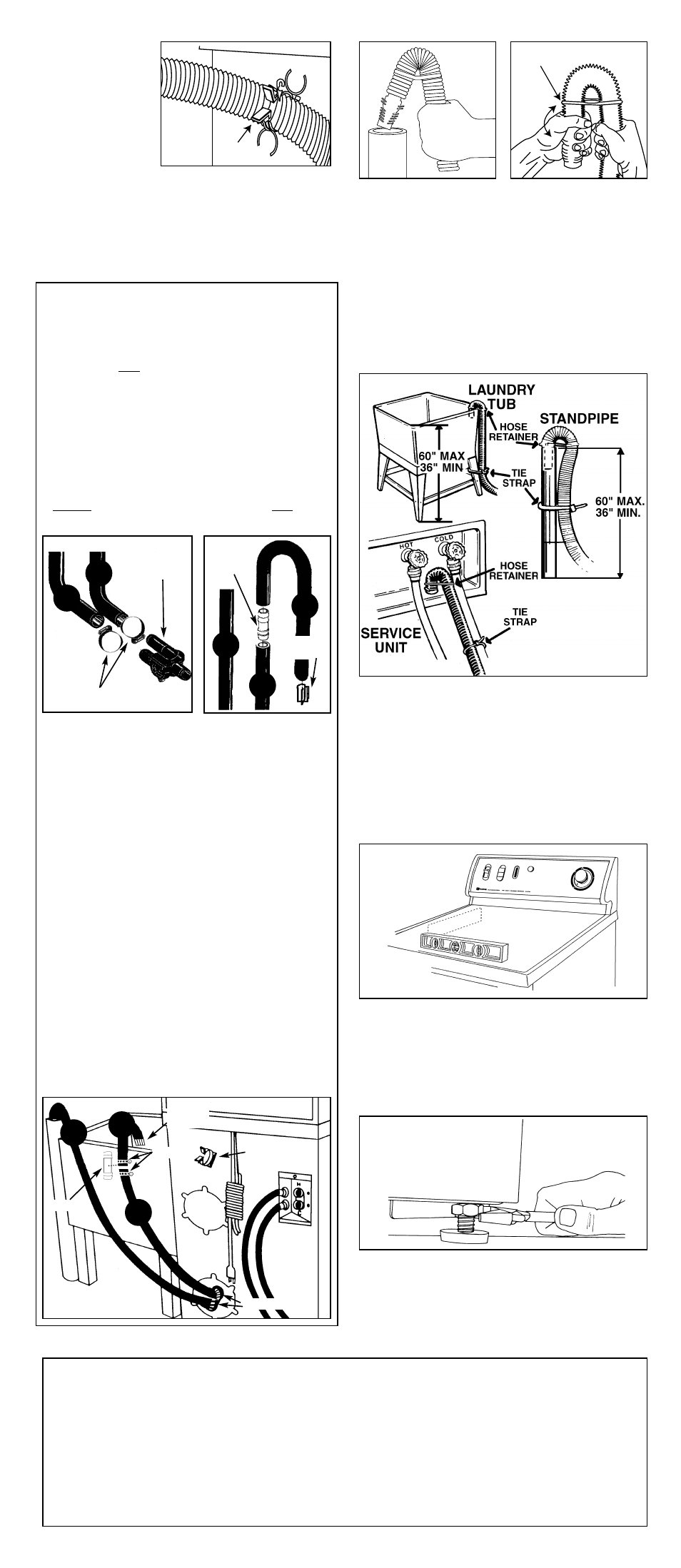
STEP 9
STANDARD MODELS
36” standpipe recommended
• If standpipe is less than 36” (or floor drain) –
drain hose should be routed through the clip
to raise hose to the proper height.
B
STEP 10a
Place the drain hose in the drain facility. If the
hose is twisted after it has been placed in the
drain, adjust the end of the hose to remove the
twist. To remove the twist, turn the short end
of the hose while holding the base of the hose
stationary.
NOTE: If you must make an airtight seal, an
antisiphon kit must be used.
STEP 11
• With a level, check washer and make
necessary adjustments to leveling legs.
STEP 12
• Once level, tighten leveling leg locking nuts
with wrench.
A
R E M I N D E R !
Proper installation is the responsibility of the purchaser.
SERVICE CALLS PERFORMED AS A RESULT OF POOR INSTALLATION ARE THE
RESPONSIBILITY OF THE INSTALLER.
For best performance the washer must be installed on a solidly constructed floor. Wood floors
may need to be reinforced to minimize vibration and/or unbalanced load situations. Carpeting
and soft tile surfaces are also contributing factors in vibration and/or tendency for a washer to
move slightly during spin cycle. Never install washer on a platform or weak supported structure.
Step 10b
To prevent accidental dislodging secure the
drain hose to the standpipe, inlet hose or
laundry tub with the tie strap provided in the
parts package.
HOSE
RETAINER
Coupler
Clamps
Clamps
Wire
Strainer
WATER SAVER MODELS
The diverter valve is located in the lower left-
hand corner on the backside of the washer.
The suds hose is a two-piece hose and con-
nects to the top diverter valve outlet. A wire
strainer is partially inserted into the end of the
gooseneck (C) to prevent sediment from
returning to the washer. The suds hose (C)
should be placed into a 21 gallon (minimum
capacity) storage tank. This hose must be
able to reach the bottom of the tank.
Installation of Hoses:
• Lower suds hose (A) connects to the top
diverter valve outlet. Use hose clamp to secure.
• Insert wire strainer into “long leg” of upper
suds hose (C).
• Install Coupler: Slide one clamp onto the
upper suds hose (C) and one clamp onto the
lower suds hose (A).
– Join the two ends of the upper (C) and
lower (A) suds hoses using the plastic
coupler. Be sure each end of the hoses are
securely pushed over the end of the
coupler…the hoses should join at approx-
imately the middle of the coupler. Use
hose clamps to secure both ends of coupler.
• Drain hose (B) connects to the bottom diverter
valve outlet. Use hose clamp to secure.
• Insert the gooseneck (B) end of the drain hose
into a 36” standpipe. NOTES: a.) If a 36”
standpipe is not available, insert the drain hose
(B) into the plastic clip on the backside of the
washer to maintain a 36” height. b.) If an air-
tight seal must be made with the standpipe, or a
floor drain is used, then an antisiphon kit must be
used.
Plastic
Clip
C
B
A
C
B
A
Coupler
Hose
Clamps
Wire
Strainer
Diverter
Valve