G. bender bar (figure 24), F. head/clincher alignment (figures 22, 23) – MBM Corporation BINDERYMATE 2 User Manual
Page 24
22
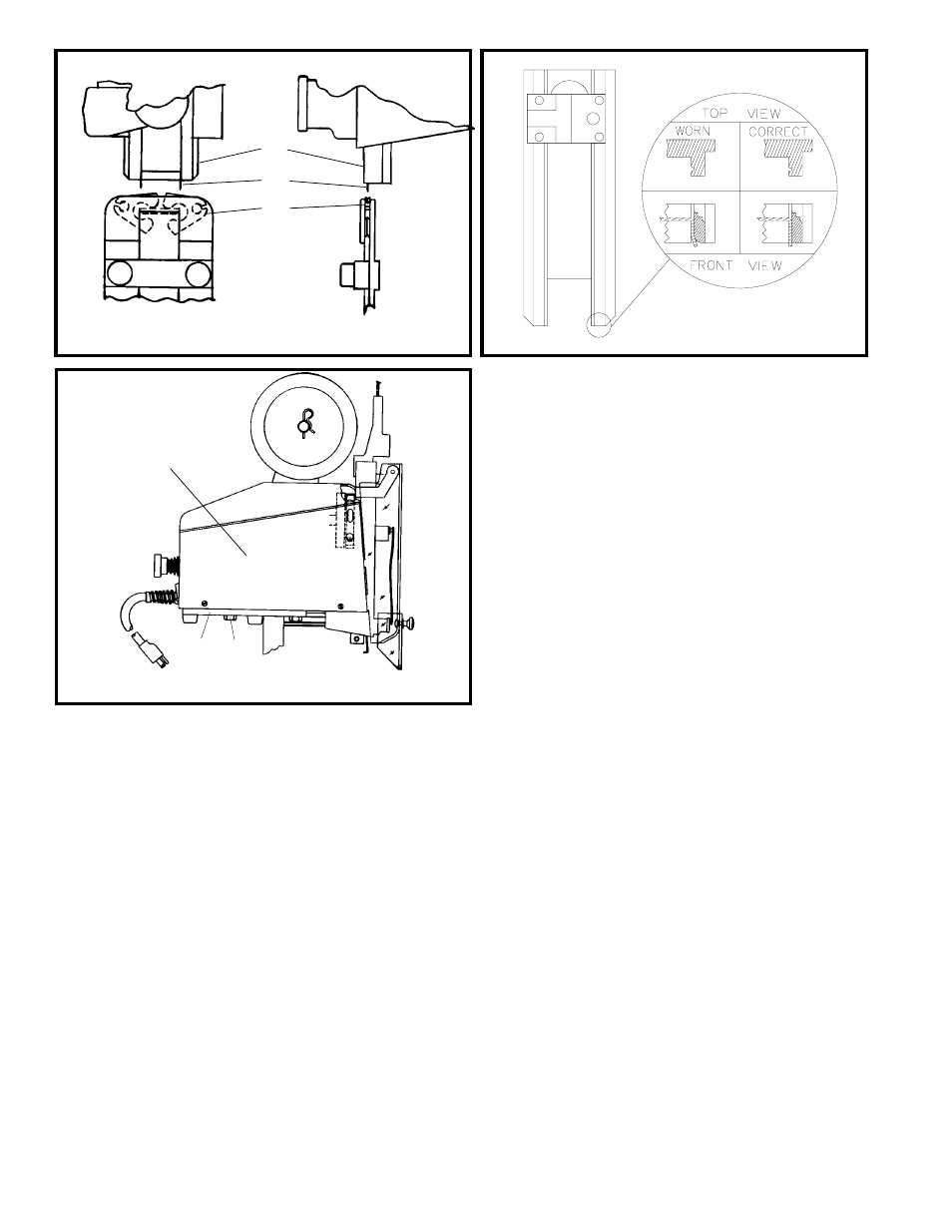
G. Bender Bar (Figure 24)
The bender bar bends the wire over the rotator and
forms it into an unclinched stitch. The legs of the
stitch are guided towards the work material by the
bender bar grooves. The legs of the unclinched
stitch should be perpendicular to the crown. When
the bender bar grooves become worn, the legs tend
to flare out (Figure 24) as they emerge from the
grooves. This causes the legs to strike the clincher
improperly. As a result, one or both legs will
crumple and a broken driver bar or a broken bender
bar can result. If the lower end of the bender bar
groove becomes chipped, it will not support the
wire and may cause the stitch to break at the crown.
Replace the bender bar assembly (See Section H or
Fig. 25). Other bender bar functions are related to
wire cutting (Section L), and driving (Section I).
H. Bender Bar Friction Plug
And/Or Spring (Fig. 25)
Two parts furnish pressure to coordinate movement
of driver bar and bender bar. If pressure is
insufficient, proper timing is not maintained for the
action of the grip. As a result, wire feeds backwards.
Replace the plug and/or spring.
To replace bender bar friction plug and/or bender
bar friction spring:
1. Remove bender bar assembly by following steps
1 through 23 of "Removing and Dismantling
M2000 Head", Pages 29 and 30.
F. Head/Clincher Alignment
(Figures 22, 23)
To test alignment: Drive several stitches into a
section of material identical to that which is to be
stitched. The clinched legs should be identical and
aligned with each other. If the legs are not in
alignment, make the following adjustments:
1. With power off, press in and turn the jog knob
clockwise until the legs of the stitch (Index A,
Fig. 22) appear just below the bender bar (Index
B).
2. Loosen the four bolts (Index A, Fig. 23) securing
the base (Index B) to the stand (Index C).
3. Move the base until the legs of the stitch line
up with the clincher points (Index C, Fig. 22).
4. Tighten the four base mounting bolts.
Figure 22
(QF27F12)
Figure 23
(QF27F13)
Figure 24
(SK852I)
A
B
C
B
C
A