6 connector diagram – Measurement Computing CIO-INT-32 User Manual
Page 11
3.6
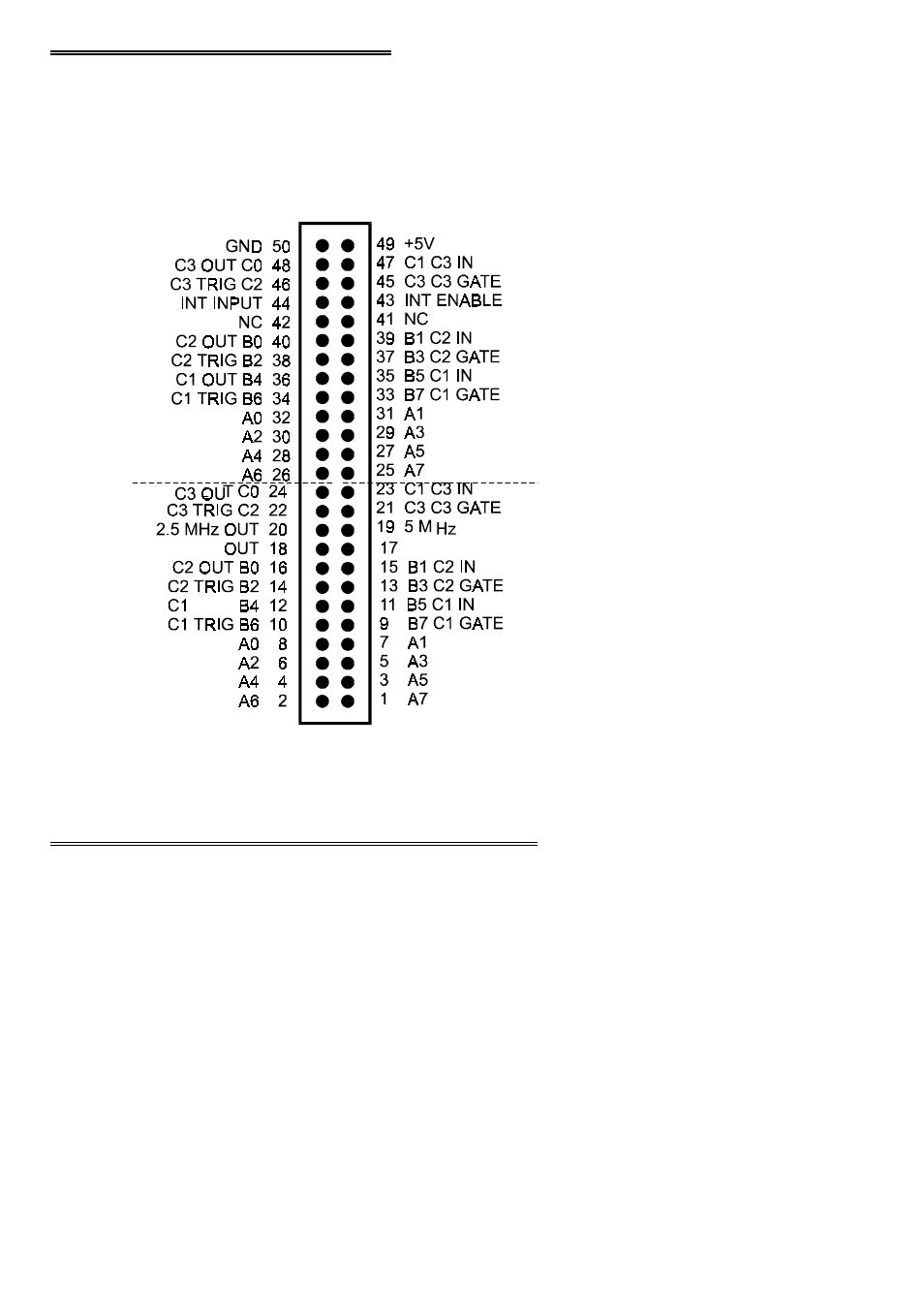
CONNECTOR DIAGRAM
The CIO-INT32 I/O connector is a 50 pin header type connector accessible from the
rear of the PC through the expansion backplate. The signals available are direct
connections to a Z8536 digital I/O chip.
If frequent changes to signal connections or signal conditioning is required, please
refer to catalog information on the CIO-MINI50 screw terminal board.
3.7
Z8536 CONTROL & DATA REGISTERS
Each CIO-INT32 is composed of two Z8536 parallel I/O chips. Each chip contains
three data and one control register occupying four consecutive I/O locations.
Complete programming and interface information is included in the Zilog Z8536
manuals.
Control and output of the Z8536 chips is accomplished by I/O writes, status and inputs
may be read from I/O ports.
7
OUT/
INTA
INTB OUT
FIRST Z8536
BASE + 0, 1, 2
SECOND Z8536
BASE + 4, 5, 6